Arduino NANO (7) ADS1115 for A/D できたので、行きよいでOLEDの表示も追加した。
( WeMos (b9) ADS1115 for A/D )とほぼ同じプログラムだが、なぜかうまく表示する、どうして?

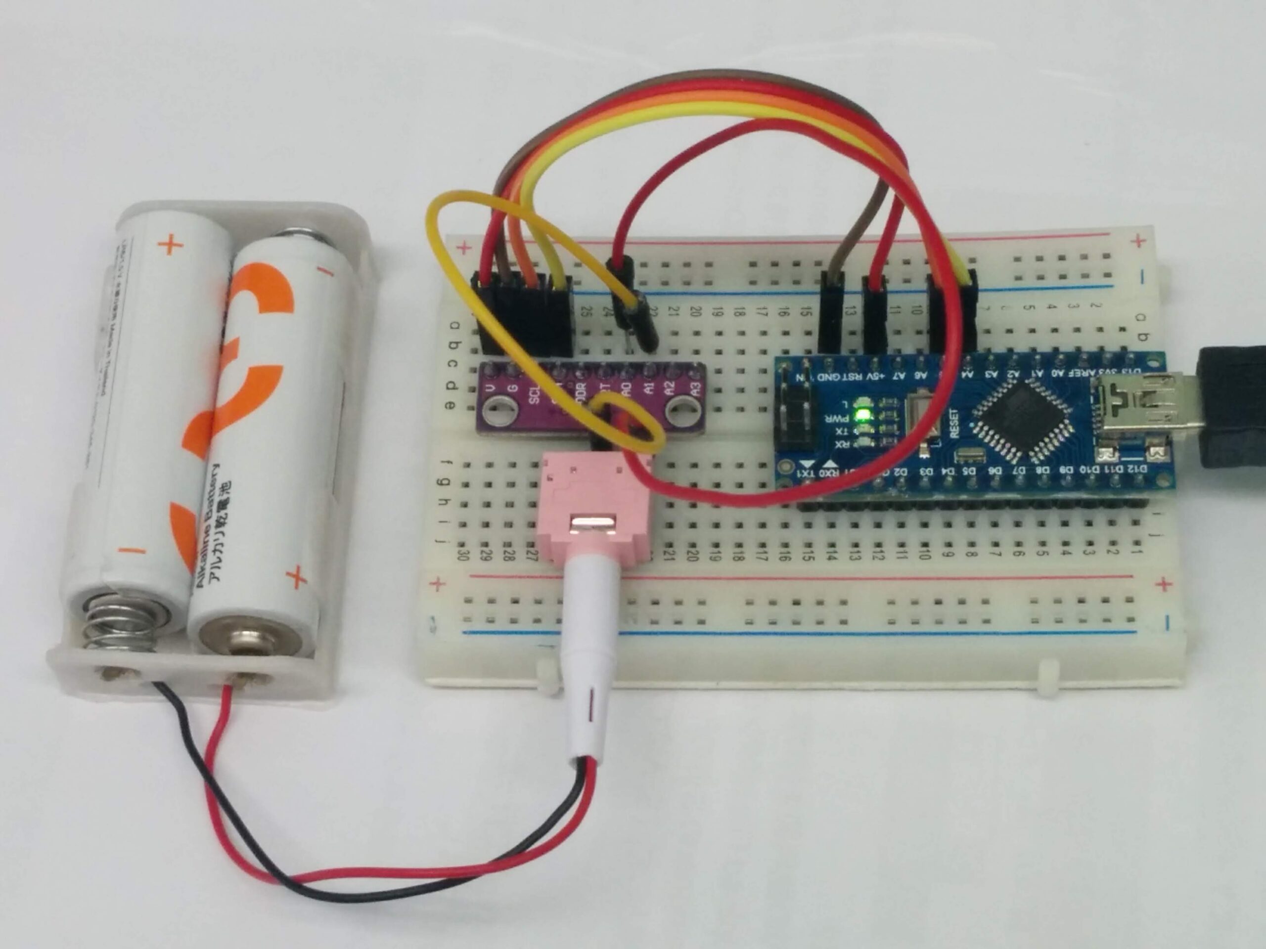
表示されるのは2本古い電池の電圧を測る値。
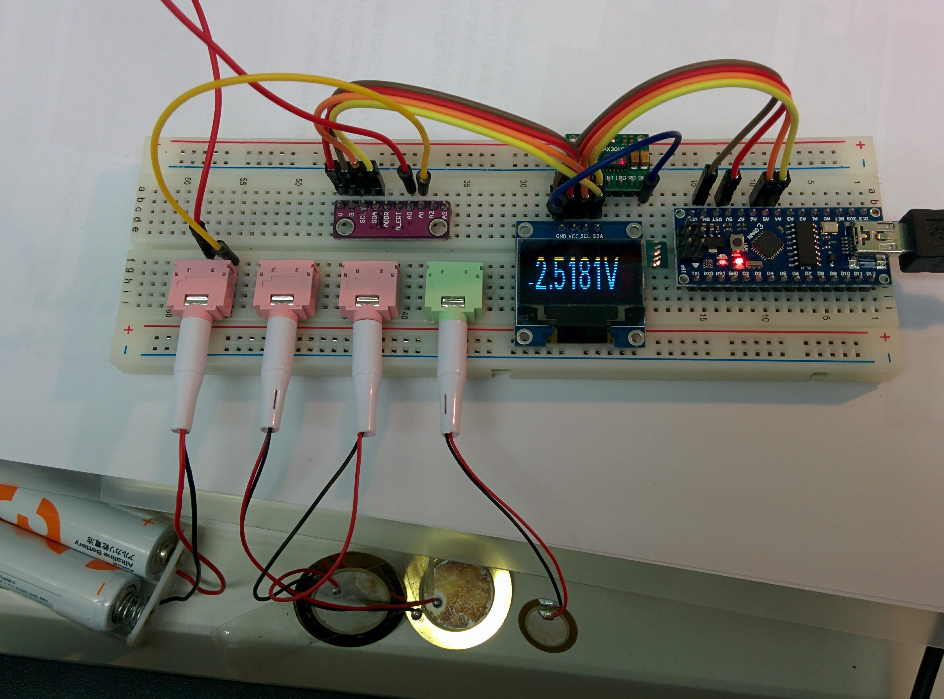
今度ピエゾの電圧も測ってみる。
Arduino NANO (7) ADS1115 for A/D できたので、行きよいでOLEDの表示も追加した。
( WeMos (b9) ADS1115 for A/D )とほぼ同じプログラムだが、なぜかうまく表示する、どうして?
表示されるのは2本古い電池の電圧を測る値。
今度ピエゾの電圧も測ってみる。
Arduino NANO (7) ADS1115 for A/D できたので、行きよいでOLEDの表示も追加した。
( WeMos (b9) ADS1115 for A/D )とほぼ同じプログラムだが、なぜかうまく表示する、どうして?
表示されるのは2本古い電池の電圧を測る値。
今度ピエゾの電圧も測ってみる。
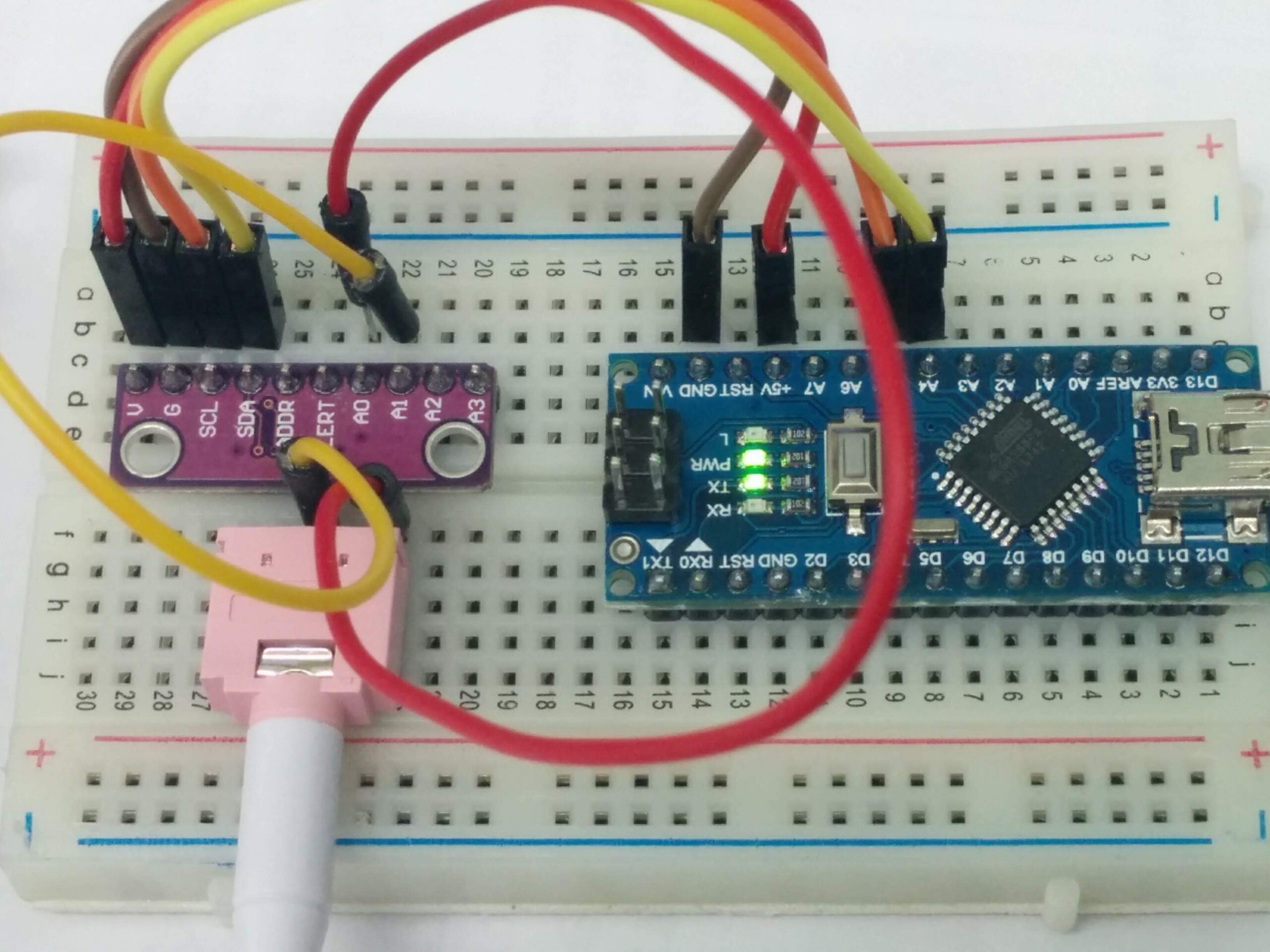
ADS1115を購入して、生体信号のAD変換に利用するつもりだが、うまくいかない( WeMos (b9) ADS1115 for A/D 参考)、正しい電圧が表示されない。
そこで、Arduino NANOのチュートリアルを探して、検証することに。
ADS1115とArduino NANOはI2Cで接続。
「参考1」コードそのまま。
#include <Wire.h>
#include <Adafruit_ADS1015.h>

Adafruit_ADS1115 ads;  // Declare an instance of the ADS1115

int16_t rawADCvalue;  // The is where we store the value we receive from the ADS1115
float scalefactor = 0.1875F; // This is the scale factor for the default +/- 6.144 Volt Range we will use
float volts = 0.0; // The result of applying the scale factor to the raw value

void setup(void)
{
  Serial.begin(9600);
  ads.begin();
}

void loop(void)
{

  rawADCvalue = ads.readADC_Differential_0_1();
  volts = (rawADCvalue * scalefactor)/1000.0;

  Serial.print("Raw ADC Value = ");
  Serial.print(rawADCvalue);
  Serial.print("tVoltage Measured = ");
  Serial.println(volts,6);
  Serial.println();


  delay(1000);
}
うまくいく!
電池の電圧はちゃんでシリアルモニターに表示。
http://henrysbench.capnfatz.com/henrys-bench/arduino-voltage-measurements/arduino-ads1115-differential-voltmeter-tutorial/
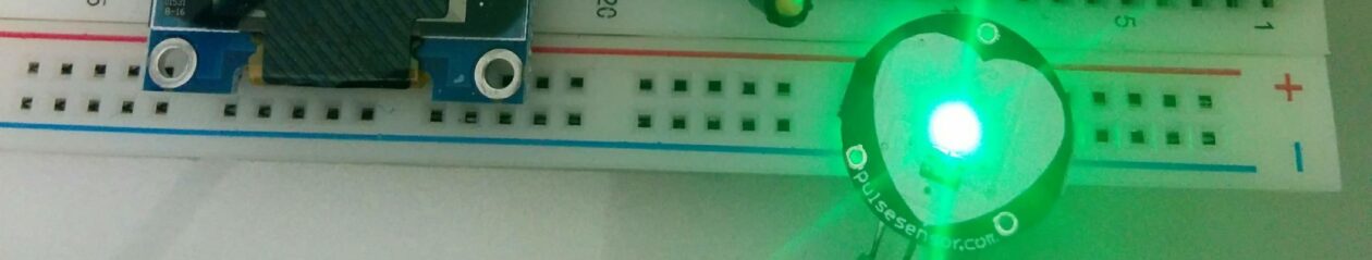
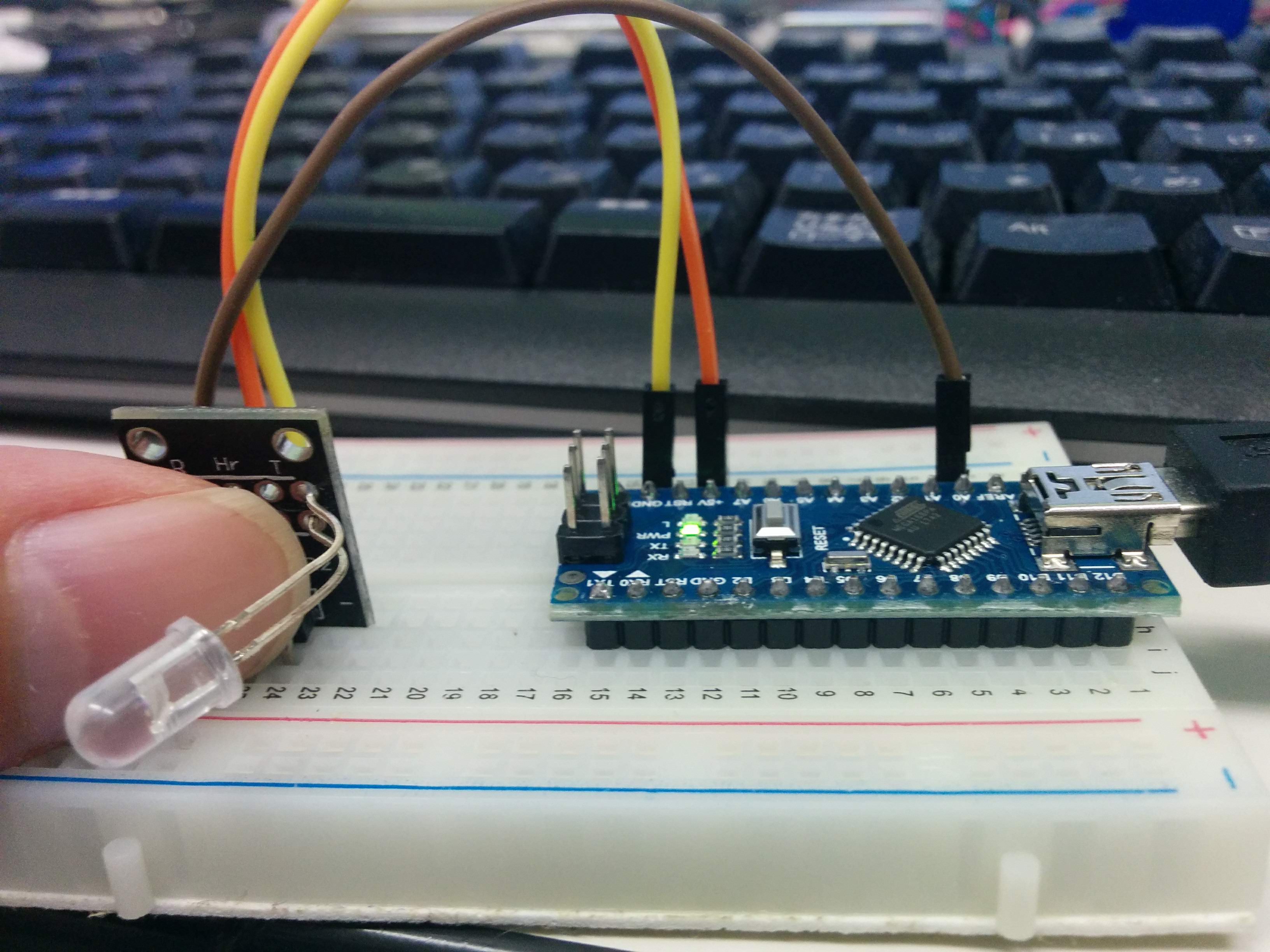
Arduinoセンサーキットに、Heart rate sensorある。
血中ヘモグロビンの近赤外線吸収の性質を利用して脈拍パルス検出するらしい。
Arduinoとの接続は3線(GND、VCC、アナログ入力)のみ。
「参考1」をみて、まず簡単の試す。ただA0の値を表示。
// Pulse Monitor Test Script
int sensorPin = 0;
void setup() {
   Serial.begin(9600);
}
void loop ()
{
   while(1)
   {
     Serial.print(analogRead(sensorPin));
     Serial.print('\n');
   }
}
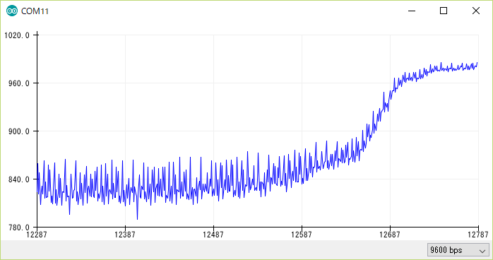
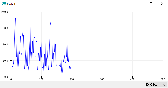
指先センサー装着
シリアルプロッターに見える上昇カーブ
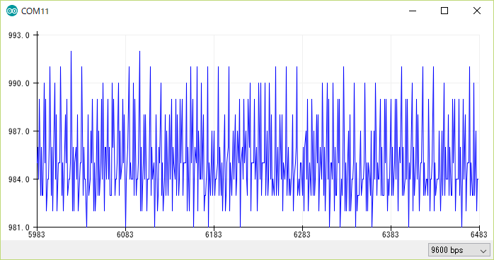
安定した状態これはなにもわからない
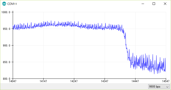
指はセンサーから離れる時の下降カーブ。
「参考1」を参考して、Smoothingしても、同じ判別不能。困った。
#define samp_siz 4
#define rise_threshold 5
// Pulse Monitor Test Script
int sensorPin = 0;
void setup() {
   Serial.begin(9600);
}
void loop ()
{
   float reads[samp_siz], sum;
   long int now, ptr;
   float last, reader, start;
   float first, second, third, before, print_value;
   bool rising;
   int rise_count;
   int n;
   long int last_beat;
   for (int i = 0; i < samp_siz; i++)
     reads[i] = 0;
   sum = 0;
   ptr = 0;
   while(1)
   {
     // calculate an average of the sensor
     // during a 20 ms period (this will eliminate
     // the 50 Hz noise caused by electric light
     n = 0;
     start = millis();
     reader = 0.;
     do
     {
       reader += analogRead (sensorPin);
       n++;
       now = millis();
     }
     while (now < start + 20);
     reader /= n;  // we got an average
     // Add the newest measurement to an array
     // and subtract the oldest measurement from the array
     // to maintain a sum of last measurements
     sum -= reads[ptr];
     sum += reader;
     reads[ptr] = reader;
     last = sum / samp_siz;
     // now last holds the average of the values in the array
     // check for a rising curve (= a heart beat)
     if (last > before)
     {
       rise_count++;
       if (!rising && rise_count > rise_threshold)
       {
         // Ok, we have detected a rising curve, which implies a heartbeat.
         // Record the time since last beat, keep track of the two previous
         // times (first, second, third) to get a weighed average.
         // The rising flag prevents us from detecting the same rise
         // more than once.
         rising = true;
         first = millis() - last_beat;
         last_beat = millis();
         // Calculate the weighed average of heartbeat rate
         // according to the three last beats
         print_value = 60000. / (0.4 * first + 0.3 * second + 0.3 * third);
         Serial.print(print_value);
         Serial.print('\n');
         third = second;
         second = first;
       }
     }
     else
     {
       // Ok, the curve is falling
       rising = false;
       rise_count = 0;
     }
     before = last;
     ptr++;
     ptr %= samp_siz;
   }
}
こんな図形になって、周囲の雑音とか酷いかな?
参考:
MAX30102 というPulse Ox Sensorを利用して、脈拍と酸素濃度を測る試み。
MAX30100の実例が多いが、MAX30102の実例が少ない。
「参考1」のSparkFunのライブラリを利用する。そのライブラリはMAX30105(R,G,IR LED)用だが、MAX30102(欠Green LED)でも利用できる。
OLED表示するため、「参考2」の表示部分を合体した。なんとなく、バグがある様な気がする。
// Sample implementation of the MAX30100 PulseOximeter
// Using the following module
// http://www.ebay.com/itm/-/391709438817?ssPageName=STRK:MESE:IT
// can not gaurantee if the app will work with other implementations of the module.

//#include "MAX30100_PulseOximeter.h"
#include <U8g2lib.h>
#include <Wire.h>
#include "MAX30105.h"
#include "heartRate.h"

#define REPORTING_PERIOD_MS     500

 U8G2_SSD1306_128X32_UNIVISION_F_HW_I2C u8g2(U8G2_R0);

// PulseOximeter is the higher level interface to the sensor
// it offers:
//  * beat detection reporting
//  * heart rate calculation
//  * SpO2 (oxidation level) calculation
//PulseOximeter pox;
MAX30105 particleSensor;

const byte RATE_SIZE = 4; //Increase this for more averaging. 4 is good.
byte rates[RATE_SIZE]; //Array of heart rates
byte rateSpot = 0;
long lastBeat = 0; //Time at which the last beat occurred

float beatsPerMinute;
int beatAvg;

//byte pulseLED = 13; //Must be on PWM pin
//byte readLED = 11; //Blinks with each data read
//
bool calculation_complete=false;
bool calculating=false;
bool initialized=false;
byte beat=0;

void show_beat()
{
  u8g2.setFont(u8g2_font_cursor_tf);
  u8g2.setCursor(8,10);
  if (beat==0) {
    u8g2.print("_");
    beat=1;
  }
  else
  {
    u8g2.print("^");
    beat=0;
  }
  u8g2.sendBuffer();
}

void initial_display()
{
  if (not initialized)
  {
    u8g2.clearBuffer();
    show_beat();
    u8g2.setCursor(24,12);
    u8g2.setFont(u8g2_font_profont15_mr);
    u8g2.print("Place finger");
    u8g2.setCursor(0,30);
    u8g2.print("on the sensor");
    u8g2.sendBuffer();
    initialized=true;
  }
}

void display_calculating(int j)
{
  if (not calculating) {
    u8g2.clearBuffer();
    calculating=true;
    initialized=false;
  }
  show_beat();
  u8g2.setCursor(24,12);
  u8g2.setFont(u8g2_font_profont15_mr);
  u8g2.print("Measuring...");
  u8g2.setCursor(0,30);
  u8g2.print(beatsPerMinute);
  u8g2.print(" Bpm");
  u8g2.sendBuffer();
}

void display_values()
{
  u8g2.clearBuffer();
  u8g2.setFont(u8g2_font_profont15_mr);

  u8g2.setCursor(0,30);
  u8g2.print(beatsPerMinute);
  u8g2.print(" Bpm _ ");
  u8g2.setCursor(65,30);
  u8g2.print(beatAvg);
  u8g2.sendBuffer();
}

void setup()
{
    Serial.begin(115200);

//    pinMode(pulseLED, OUTPUT);
//    pinMode(readLED, OUTPUT);

    u8g2.begin();

    // Initialize sensor
    if (!particleSensor.begin(Wire, I2C_SPEED_FAST)) //Use default I2C port, 400kHz speed
    {
      Serial.println(F("MAX30105 was not found. Please check wiring/power."));
      while (1);
    }

    particleSensor.setup(); //Configure sensor with default settings
    particleSensor.setPulseAmplitudeRed(0x0A); //Turn Red LED to low to indicate sensor is running
    particleSensor.setPulseAmplitudeGreen(0); //Turn off Green LED

    initial_display();
}


void loop()
{

  long irValue = particleSensor.getIR();
  float temperature = particleSensor.readTemperature();
//  digitalWrite(readLED, !digitalRead(readLED)); //Blink onboard LED with every data read

  if (checkForBeat(irValue) == true)
  {
    calculation_complete=true;
    calculating=false;
    initialized=false;

//    digitalWrite(pulseLED, !digitalRead(pulseLED)); //Blink onboard LED with every Beat
    //We sensed a beat!
    long delta = millis() - lastBeat;
    lastBeat = millis();

    if (delta < 10000) {
      beatsPerMinute = 60 / (delta / 1000.0);
    } else {
      calculation_complete=false;
      beatsPerMinute=0;
      initial_display();
    }

    if (beatsPerMinute < 255 && beatsPerMinute > 20)
    {
      rates[rateSpot++] = (byte)beatsPerMinute; //Store this reading in the array
      rateSpot %= RATE_SIZE; //Wrap variable

      //Take average of readings
      beatAvg = 0;
      for (byte x = 0 ; x < RATE_SIZE ; x++)
        beatAvg += rates[x];
      beatAvg /= RATE_SIZE;
      display_values();
    }
  } else {
    if (irValue < 50000) {
      calculating=false;
      initial_display();
    } else {
      display_calculating(5);
    }
  }

  Serial.print("IR=");
  Serial.print(irValue);
  Serial.print(", BPM=");
  Serial.print(beatsPerMinute);
  Serial.print(", Avg BPM=");
  Serial.print(beatAvg);
  Serial.print(", initialized=");
  Serial.print(initialized);
  Serial.print(", calculating=");
  Serial.print(calculating);
  Serial.print(", calculation_complete=");
  Serial.print(calculation_complete);
  Serial.println();


}
かなり不安定の感じがする。
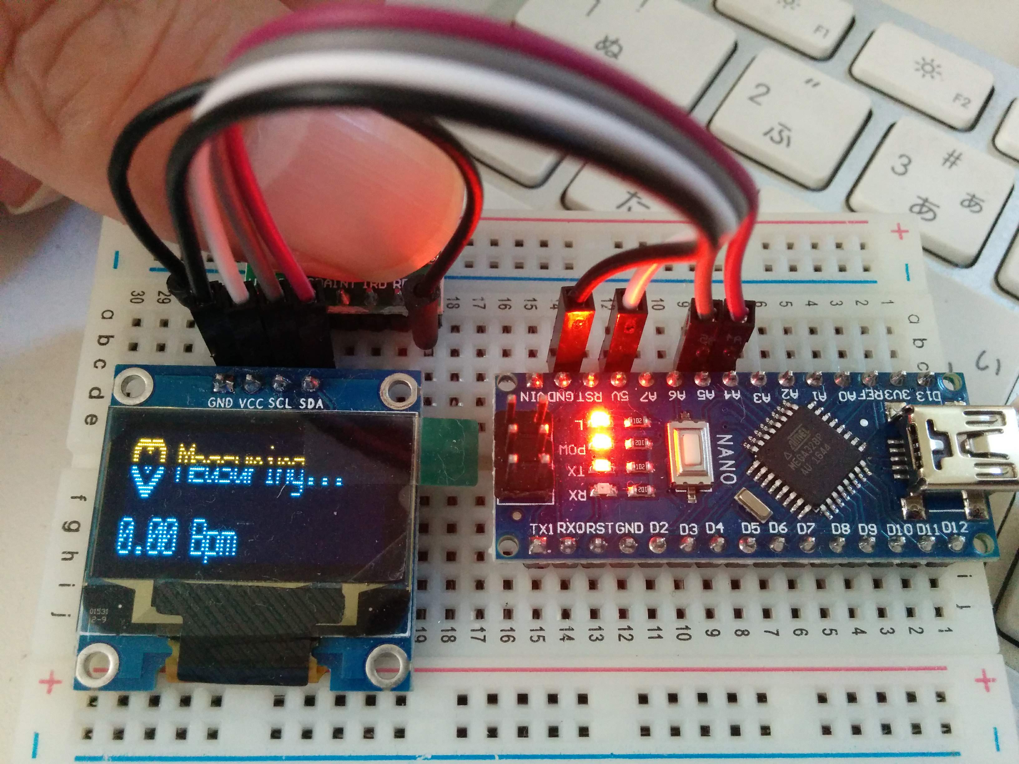
一応、形はできたが、
しかし、脈拍捉えるのは稀て、今回も失敗して。。。
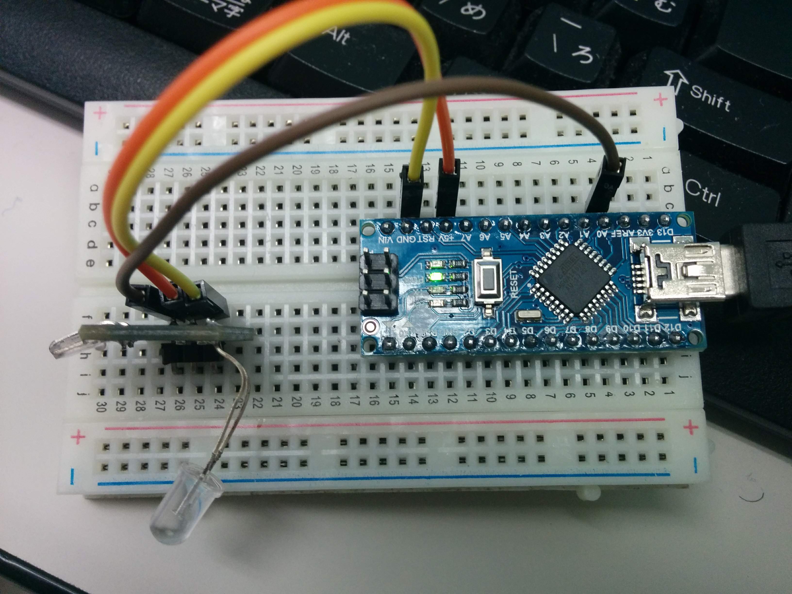
Piezoelectric sensorを利用して、住宅内の音声、振動から年配者の介護の補助を考えている。
Piezoelectric sensorが取った情報をAD変換して、簡単にWemosで処理すると思ったが、いろいろ意外なところで躓いた。
何か類似する、簡単に検証できる例がないか探した。
「参考1」から、普通のPiezoelectric sensorで、簡単に脈拍を取れると、魅力と思った。
必要な部品が揃うまで時間がかかったが、一応出来た。
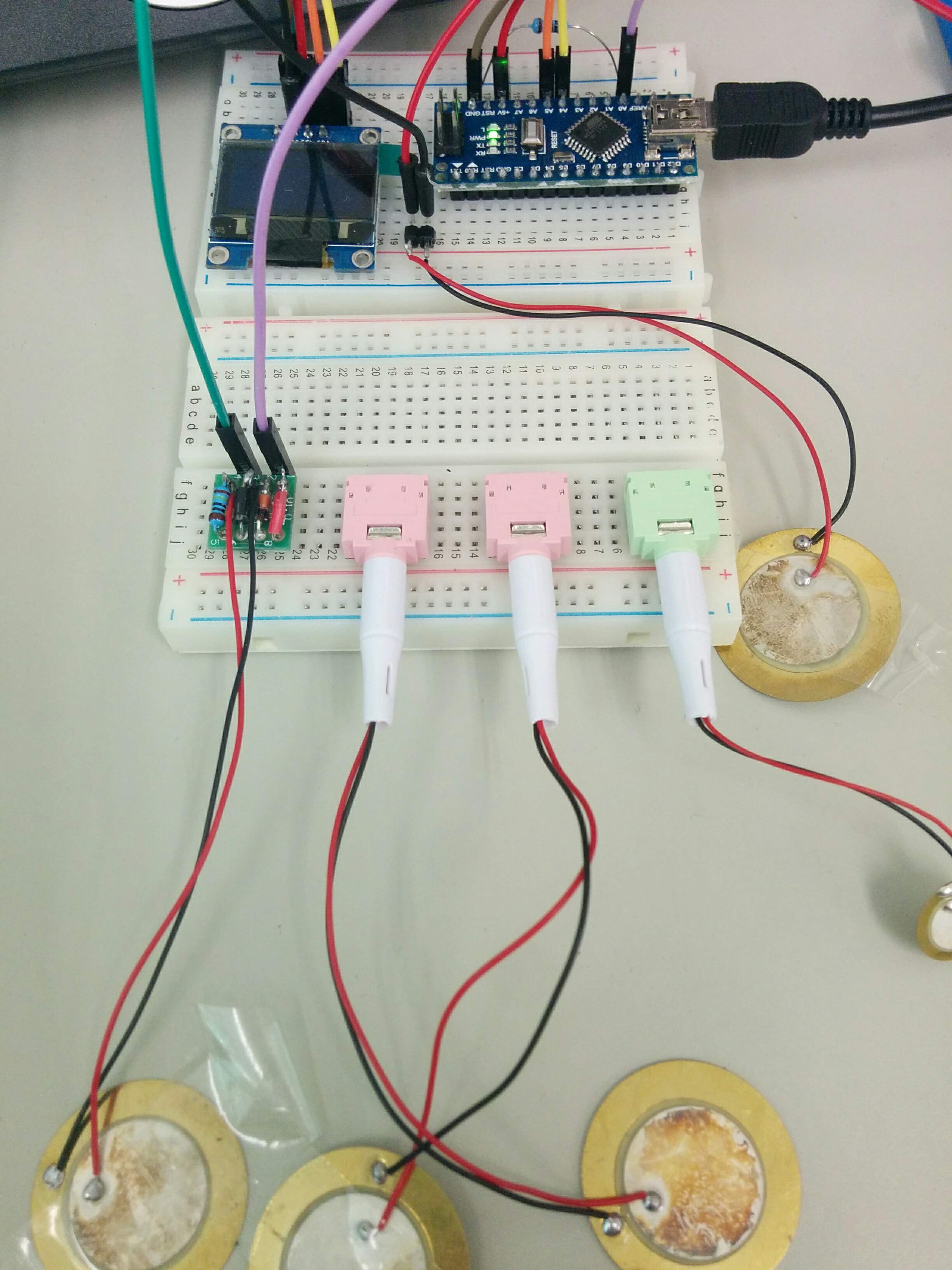
いろいろと試したところ
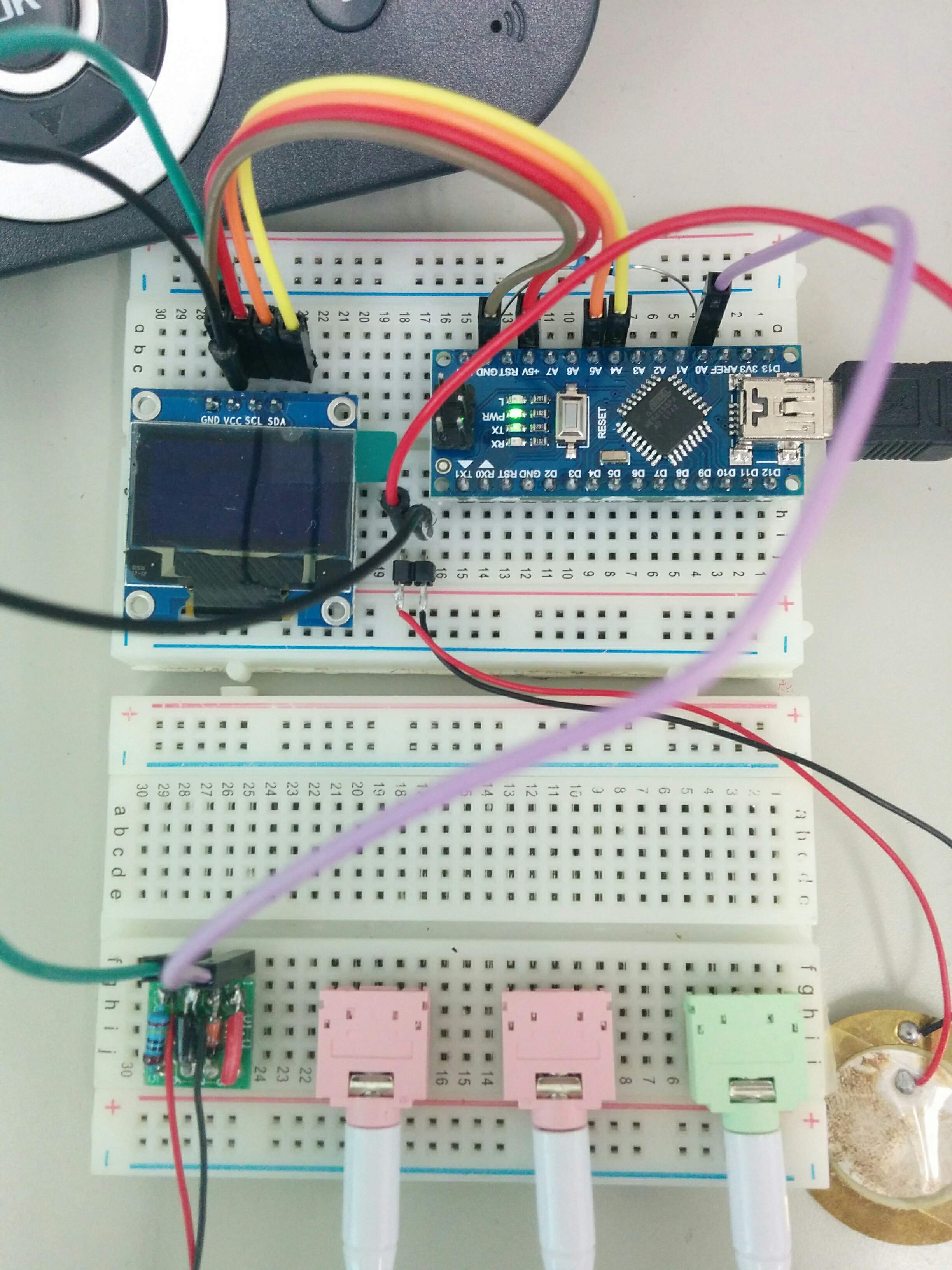
拡大写真
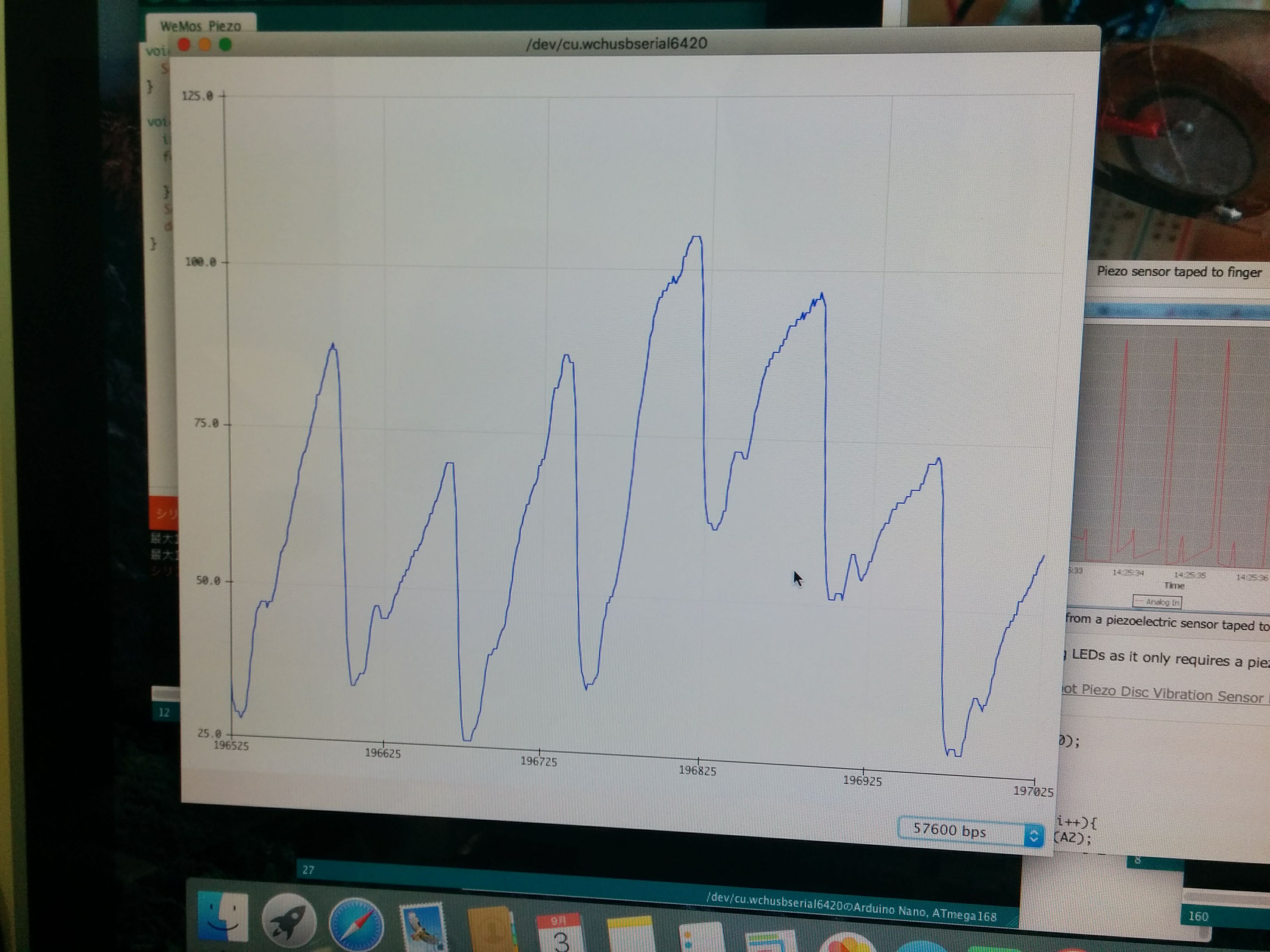
取れた波形。「参考1」の波形には似ているは、DC成分あるから、取り除くが課題。
ちょっと大き目のOLEDが欲しくて、1.3 InchのOLEDを注文した。
ただもの挿し替えて使えると思って、届いてわかったが、コントローラーは別物。SH1106というものを使われ、U8g2libライブラリをインストールして利用する。
実際参考サイトを見ながら、試してみる。

うまく表示できた。
しかしコントローラーが特殊のため、使用例がほとんど無いので、用途が限定。
#include <Arduino.h>
#include <U8g2lib.h>

#ifdef U8X8_HAVE_HW_SPI
#include <SPI.h>
#endif
#ifdef U8X8_HAVE_HW_I2C
#include <Wire.h>
#endif

U8G2_SH1106_128X64_NONAME_F_HW_I2C u8g(U8G2_R0, /* reset=*/ U8X8_PIN_NONE);
// U8GLIB_SH1106_128X64 u8g(U8G_I2C_OPT_NONE); // I2C / TWI

const uint8_t bm[] PROGMEM = {
  0b00011000,
  0b00111100,
  0b01111110,
  0b11111111,
  0b11111111,
  0b01111110,
  0b00111100,
  0b00011000
};

static int WIDTH=128;
static int HEIGHT=64;

int x, y;

void setup(void) {
  u8g.begin();
  x = 0;
  y = 0;
}

void loop(void) {

  u8g.firstPage();
  do {
    u8g.drawBitmap( x, y, 1, 8, bm);
  } while( u8g.nextPage() );

  delay(100);

  x += 8;
  if( x >= WIDTH){
    x = 0;
    y += 8;
    if( y >= HEIGHT){
      y = 0;
    }
  }
}
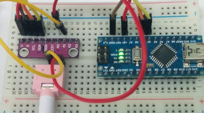
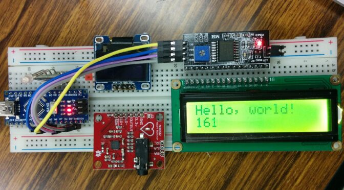
1602 LCD直接繋ぐと、6つのデジタルポートを占有(4つデータワイヤ+2の制御ワイヤが必要)し、GPIOはたくさん消耗するので、i2cを利用すると2つのアナログポートが足りる。
WeMosで試すと、うまくいかないので、より汎用のこのNANOで試す。すんなりうまくいく。
I2C インターフェイス SDA、SCL は Arduino Nano ではそれぞれ A4、A5 です。
| Arduino Nano | |
|---|---|
| SDA | A4 |
| SCL | A5 |
サンプルプログラム。
#include <LiquidCrystal_I2C.h>

LiquidCrystal_I2C lcd(0x27,16,2);

void setup() {
  lcd.init();
  lcd.backlight();
  lcd.setCursor(0, 0);
  lcd.print("Hello, world!");
}

void loop(){
  // set the cursor to column 0, line 1
  // (note: line 1 is the second row, since counting begins with 0):
  lcd.setCursor(0, 1);
  // print the number of seconds since reset:
  lcd.print(millis() / 1000);
}
写真も後ほどに。

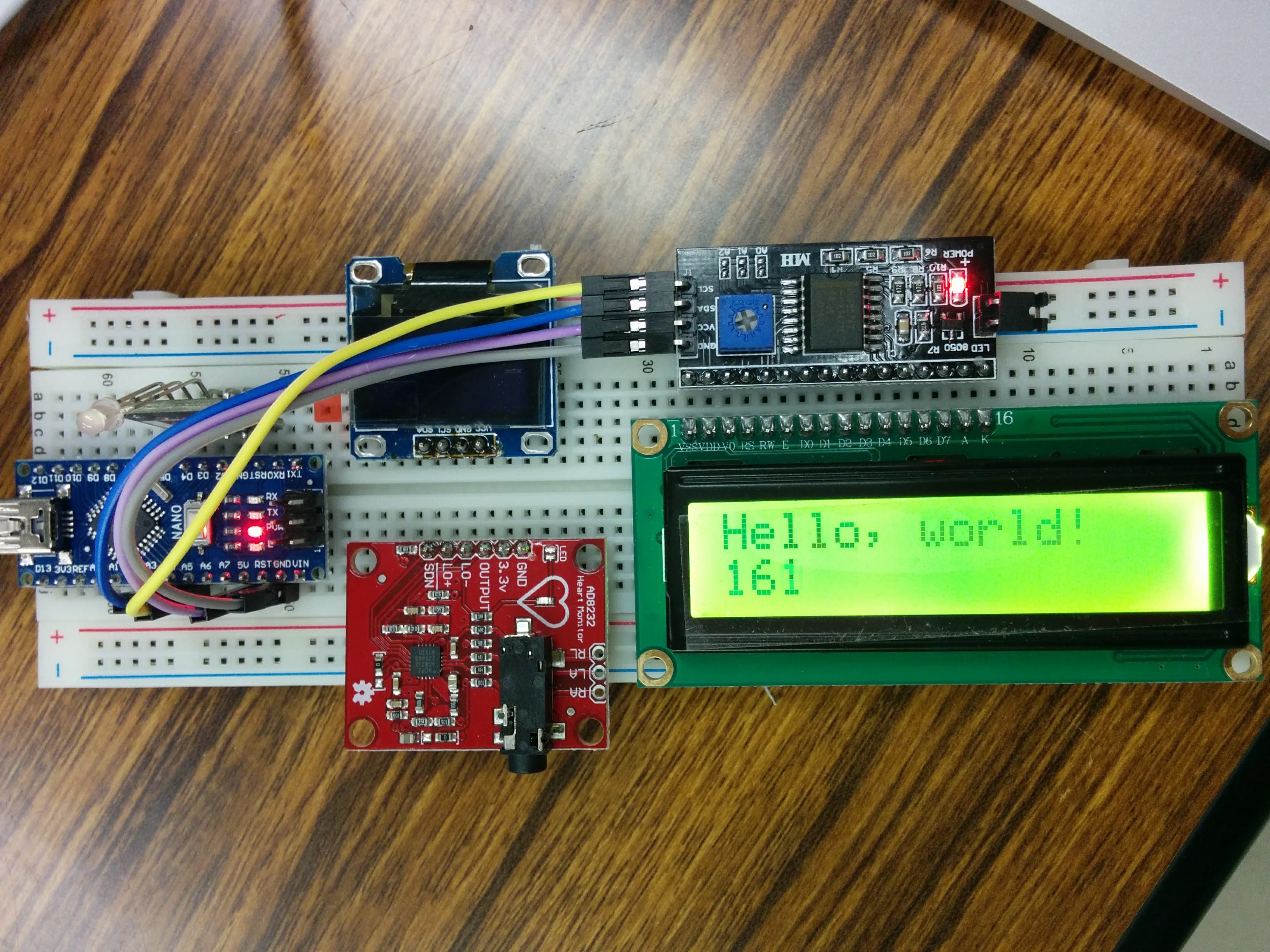
IoT材料を探しに、AD8232 Heart Rate Monitor パーツを購入しました。
添付資料は何もないので、ネットで検索したら、結構出ました。
目の動きも検出できる、いろいろできそう。
参考資料は、Arduino NANOを利用するので、そのままの回路を組み立てる予定。成功したら、ESP8266,ESP32に移植するつもり。
The detailed specification of the Arduino Nano board is as follows:
Arduino NANOとAD8232をつないて、LCDまたはOLEDで表示するつもりだが、安定した結果は出ないので、部品の問題か、ソフトウェアの問題か、解決に難航。
部品を買い増すして、検証する予定。