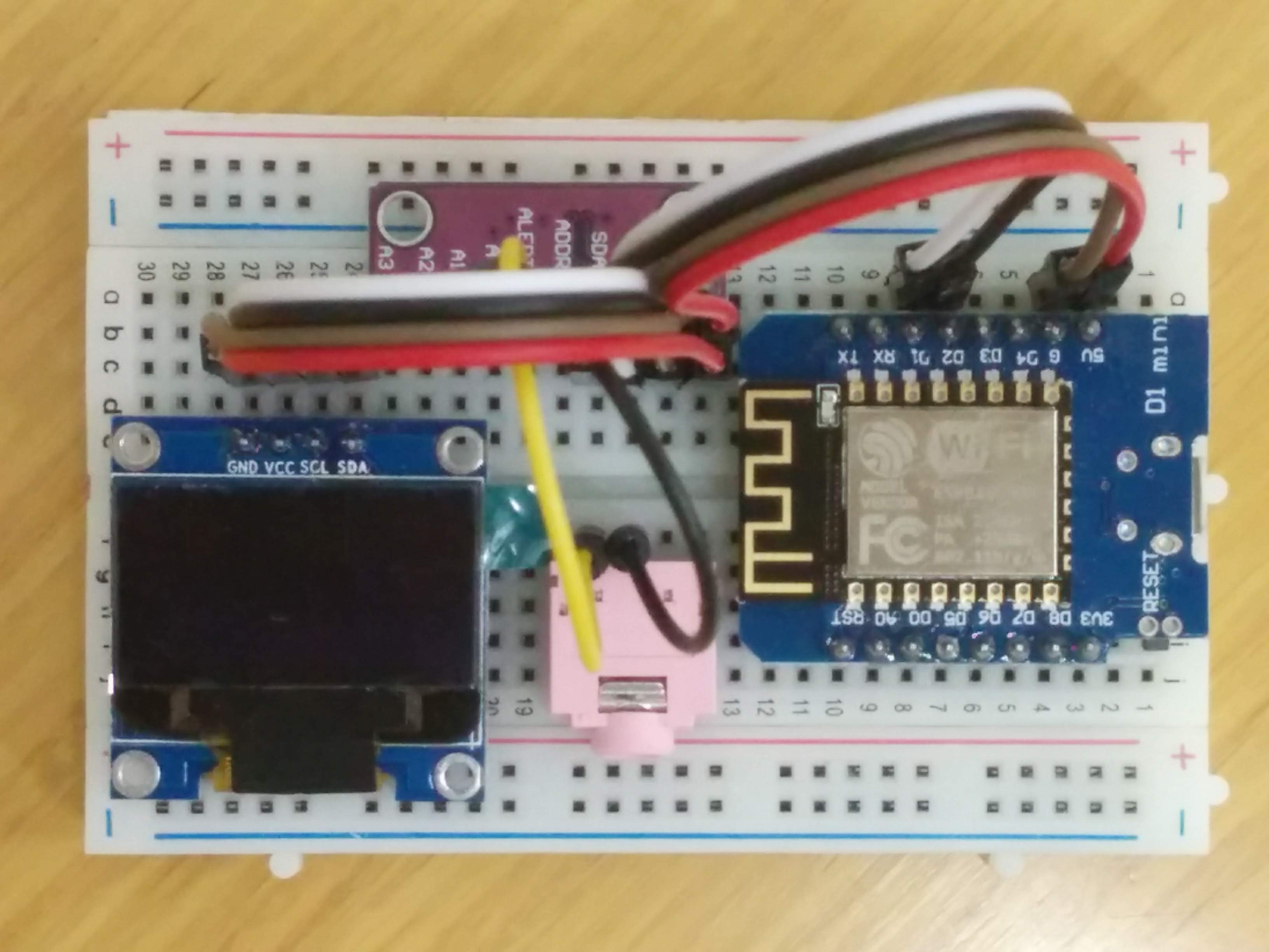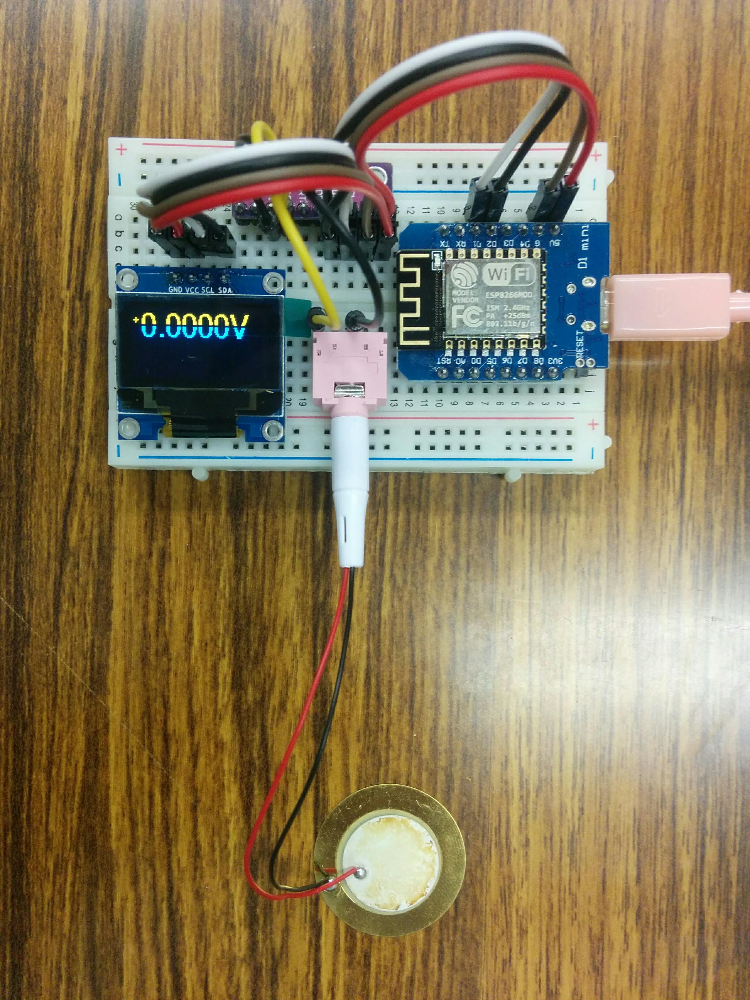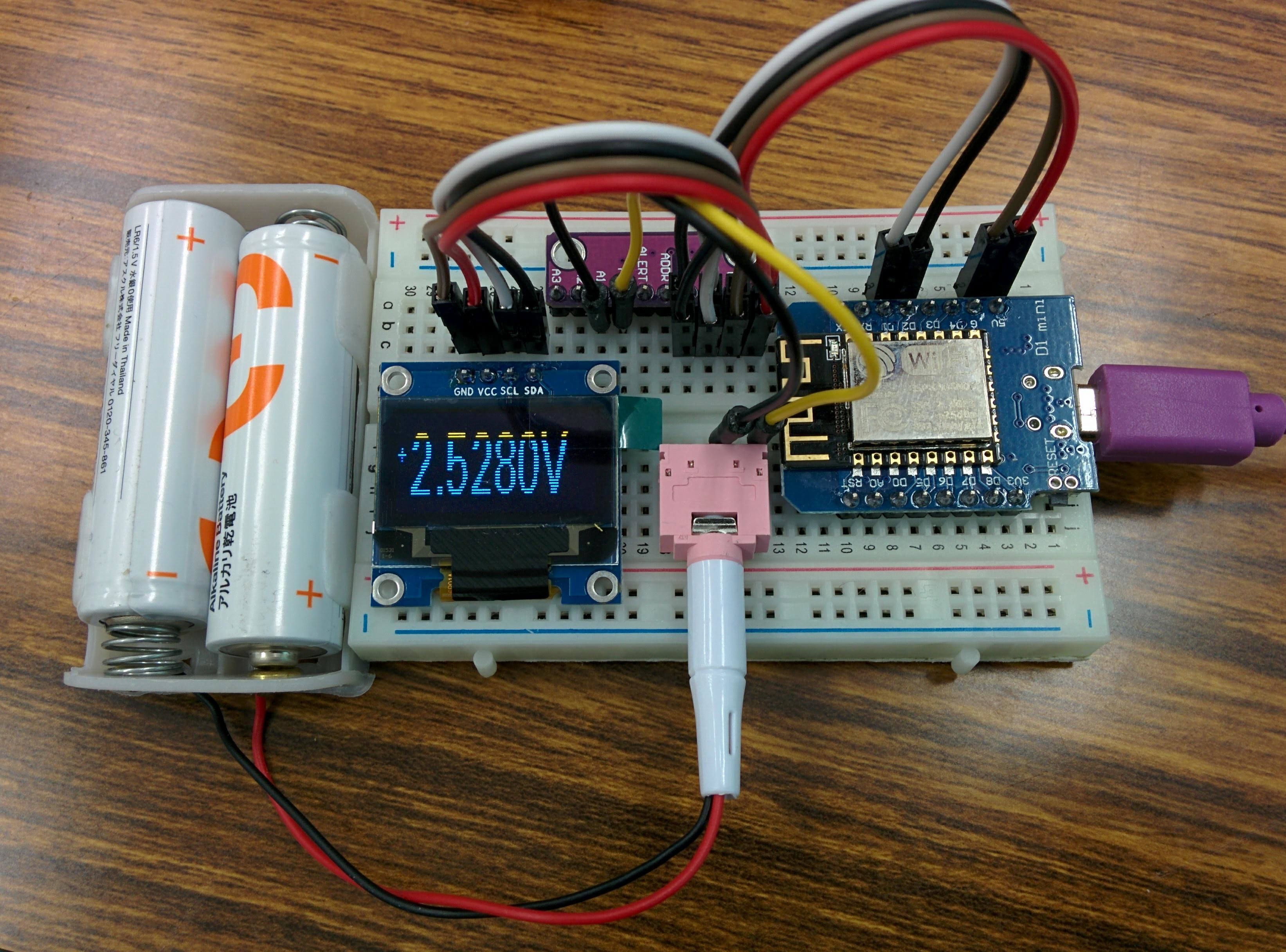
前回WeMos (b9) ADS1115 for A/Dで数値の表示ができたが、Oscilloscopeのような表示すべく、改造を試み。
しかし、2月から、WeMos miniの開発中も頻繁にリブートしています。デバイストライバのバージョンを変えたり、OSを変えたりしても改善しない。
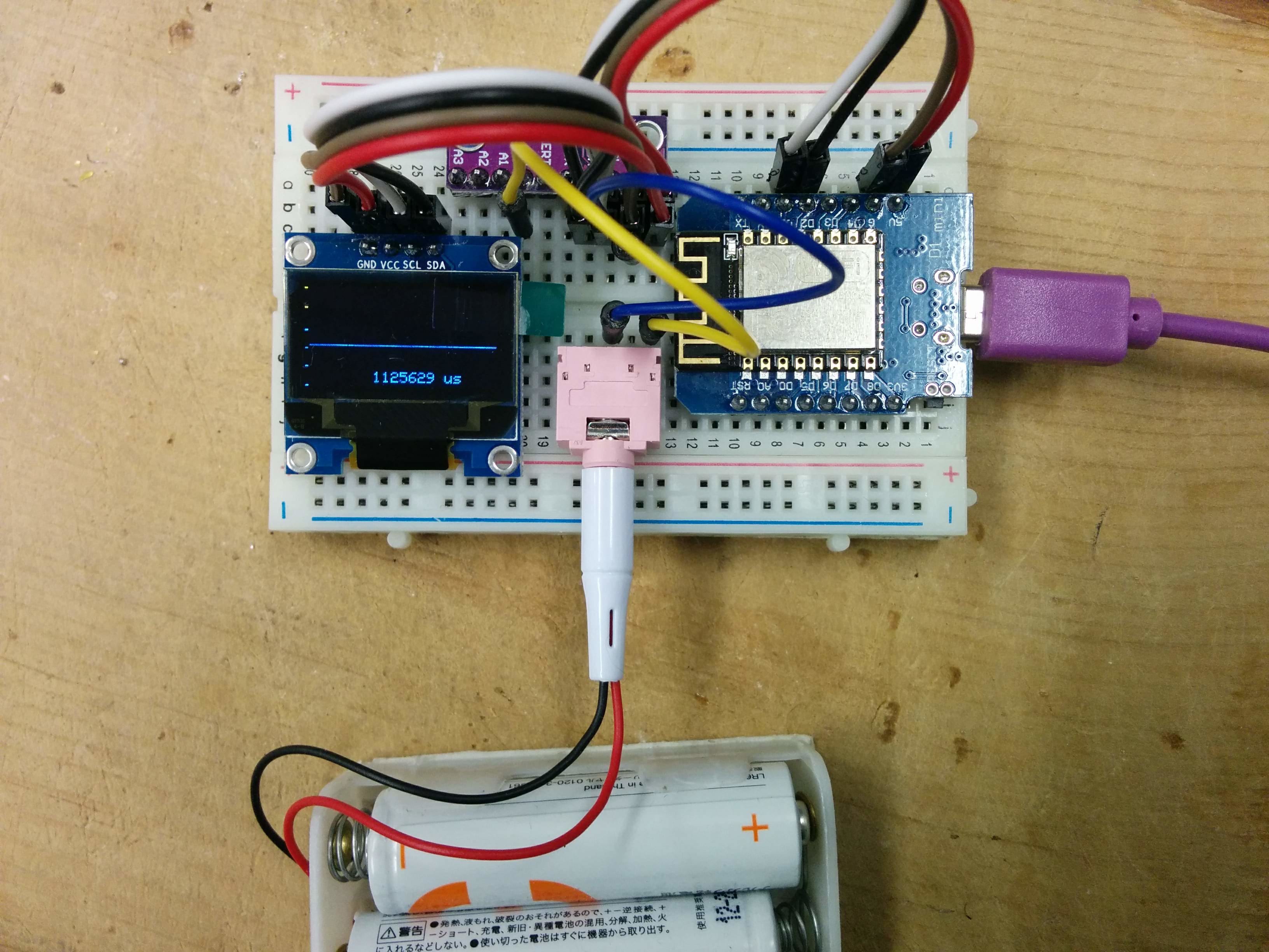
そのため、このプログラムは未完成のまま放置。
/*
This is set up to use a 128x64 I2C screen, as available
here: http://www.banggood.com/buy/0-96-oled.html
For wiring details see http://youtu.be/XHDNXXhg3Hg
*/
#include <SPI.h>
#include <Wire.h>
#include <limits.h>
#include <Adafruit_GFX.h>
#include <Adafruit_SSD1306.h>
#include <Adafruit_ADS1015.h>
#include <math.h>
#define WINDOW_SIZE 128
Adafruit_ADS1115 ads;  /* Use this for the 16-bit version */
//Adafruit_ADS1015 ads;     /* Use thi for the 12-bit version */
#define OLED_RESET 0    // 4
Adafruit_SSD1306 display(OLED_RESET);
#if (SSD1306_LCDHEIGHT != 64)
//  error("Height incorrect, please fix Adafruit_SSD1306.h!");
#endif
/********************************************/
#define CHARWIDTH           5
#define CHARHEIGHT          8
#define AXISWIDTH           (2 + 1)                   // axis will show two-pixel wide graph ticks, then an empty column
#define VISIBLEVALUEPIXELS  (128 - AXISWIDTH)         // the number of samples visible on screen
#define NUMVALUES           (2 * VISIBLEVALUEPIXELS)  // the total number of samples (take twice as many as visible, to help find trigger point
#define TRIGGER_ENABLE_PIN       D6  // 2 set this pin high to enable trigger
#define SCREEN_UPDATE_ENABLE_PIN D8  // 3 set this pin high to freeze screen
byte values[NUMVALUES];           // stores read analog values mapped to 0-63
int pos = 0;                      // the next position in the value array to read
int count = 0;                    // the total number of times through the loop
unsigned long readStartTime = 0;  // time when the current sampling started
int sampleRate = 1;              // A value of 1 will sample every time through the loop, 5 will sample every fifth time etc.
// Draws the graph ticks for the vertical axis
void drawAxis()
{
  // graph ticks
  for (int x = 0; x < 2; x++) {
    display.drawPixel(x,  0, WHITE);
    display.drawPixel(x, 13, WHITE);
    display.drawPixel(x, 26, WHITE);
    display.drawPixel(x, 38, WHITE);
    display.drawPixel(x, 50, WHITE);
    display.drawPixel(x, 63, WHITE);
  }
}
// Draws the sampled values
void drawValues()
{
  int start = 0;
  if ( digitalRead(TRIGGER_ENABLE_PIN) ) {
    // Find the first occurence of zero
    for (int i = 0; i < NUMVALUES; i++) {
      if ( values[i] == 0 ) {
        // Now find the next value that is not zero
        for (; i < NUMVALUES; i++) {
          if ( values[i] != 0 ) {
            start = i;
            break;
          }
        }
        break;
      }
    }
    // If the trigger point is not within half of our values, we will
    // not have enough sample points to show the wave correctly
    if ( start >= VISIBLEVALUEPIXELS )
      return;
  }
  for (int i = 0; i < VISIBLEVALUEPIXELS; i++) {
    display.drawPixel(i + AXISWIDTH, 63 - (values[i + start]), WHITE);
  }
}
// Shows the time taken to sample the values shown on screen
void drawFrameTime(unsigned long us)
{
  display.setCursor(9 * CHARWIDTH, 7 * CHARHEIGHT - 2); // almost at bottom, approximately centered
  display.print(us);
  display.println(" us");
}
/********************************************/
void setup() {
  // The ADC input range (or gain) can be changed via the following
  // functions, but be careful never to exceed VDD +0.3V max, or to
  // exceed the upper and lower limits if you adjust the input range!
  // Setting these values incorrectly may destroy your ADC!
  //                                                                ADS1015  ADS1115
  //                                                                -------  -------
     ads.setGain(GAIN_TWOTHIRDS);  // 2/3x gain +/- 6.144V  1 bit = 3mV      0.1875mV (default)
  // ads.setGain(GAIN_ONE);        // 1x gain   +/- 4.096V  1 bit = 2mV      0.125mV
  // ads.setGain(GAIN_TWO);        // 2x gain   +/- 2.048V  1 bit = 1mV      0.0625mV
  // ads.setGain(GAIN_FOUR);       // 4x gain   +/- 1.024V  1 bit = 0.5mV    0.03125mV
  // ads.setGain(GAIN_EIGHT);      // 8x gain   +/- 0.512V  1 bit = 0.25mV   0.015625mV
  // ads.setGain(GAIN_SIXTEEN);    // 16x gain  +/- 0.256V  1 bit = 0.125mV  0.0078125mV
  ads.begin();
  // Set up the display
  display.begin(SSD1306_SWITCHCAPVCC, 0x3C); // Initialize with the I2C addr 0x3D (for the 128x64)
  display.setTextColor(WHITE);
  pinMode(TRIGGER_ENABLE_PIN, INPUT);
  pinMode(SCREEN_UPDATE_ENABLE_PIN, INPUT);
}
/********************************************/
void loop() {
  // If a sampling run is about to start, record the start time
  if ( pos == 0 )
    readStartTime = micros();
  // If this iteration is one we want a sample for, take the sample
  if ( (++count) % sampleRate == 0 )
    values[pos++] = (ads.readADC_SingleEnded(0)>> 7) / 3; // shifting right by 4 efficiently maps 0-1023 range to 0-63
//    values[pos++] = analogRead(0) >> 4; // shifting right by 4 efficiently maps 0-1023 range to 0-63
  // If we have filled the sample buffer, display the results on screen
  if ( pos >= NUMVALUES ) {
    // Measure how long the run took
    unsigned long totalSampleTime = (micros() - readStartTime) / 2;     // Divide by 2 because we are taking twice as many samples as are shown on the screen
    if ( !digitalRead(SCREEN_UPDATE_ENABLE_PIN) ) {
      // Display the data on screen
      display.clearDisplay();
      drawAxis();
      drawValues();
      drawFrameTime(totalSampleTime);
      display.display();
    }
    // Reset values for the next sampling run
    pos = 0;
    count = 0;
  }
}