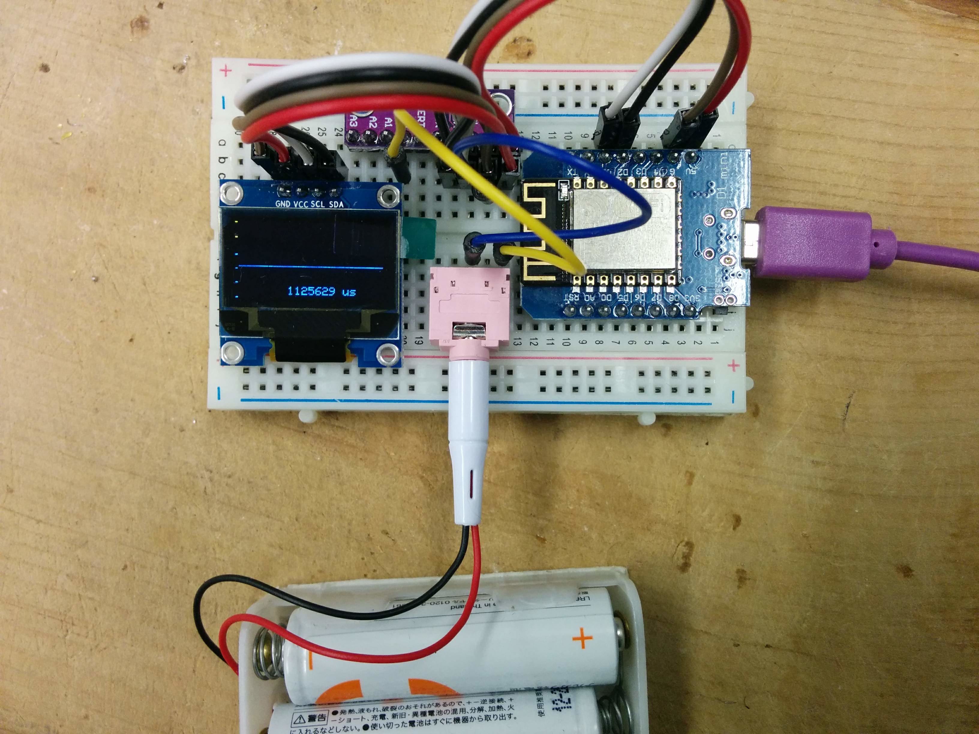
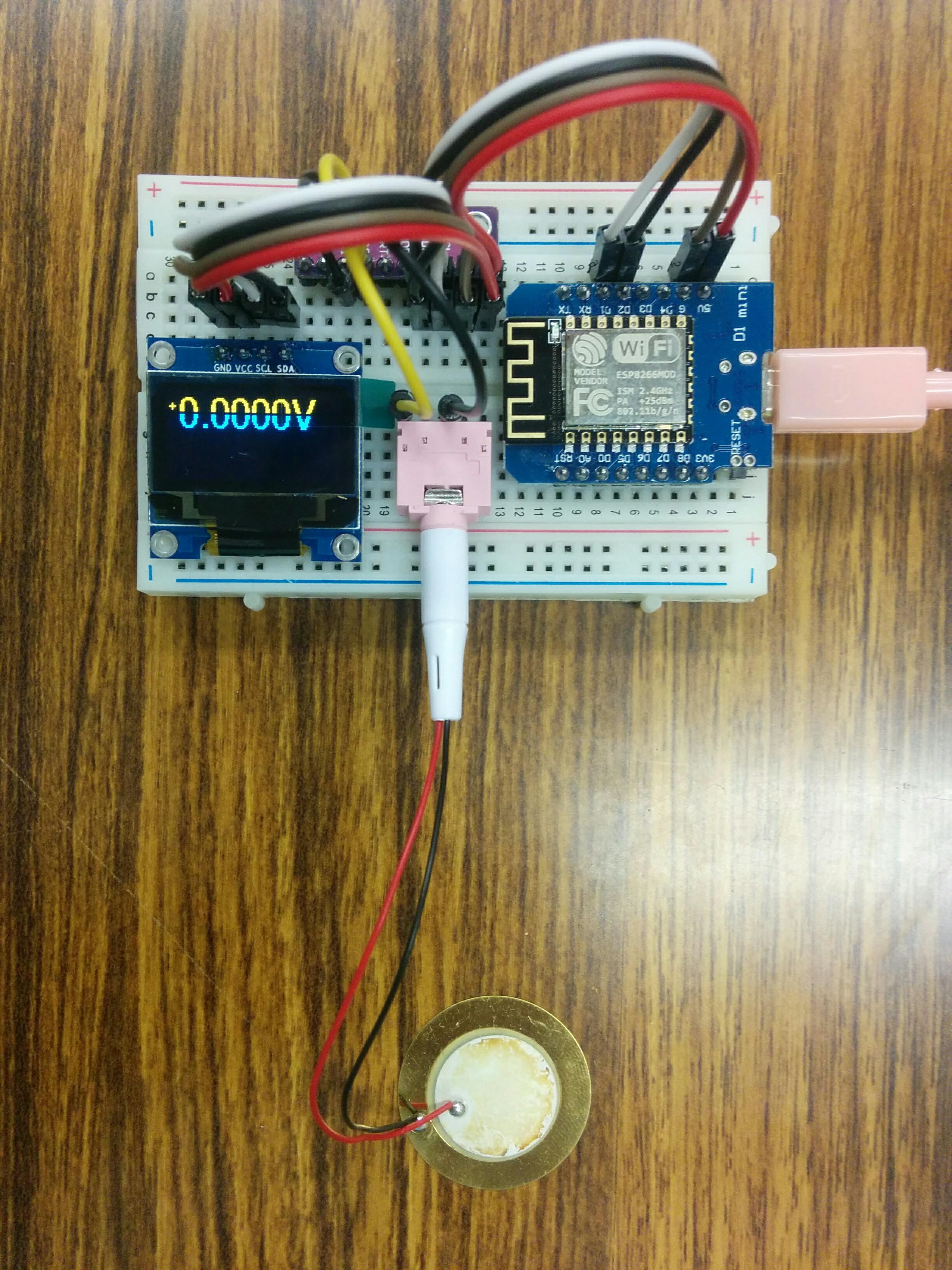
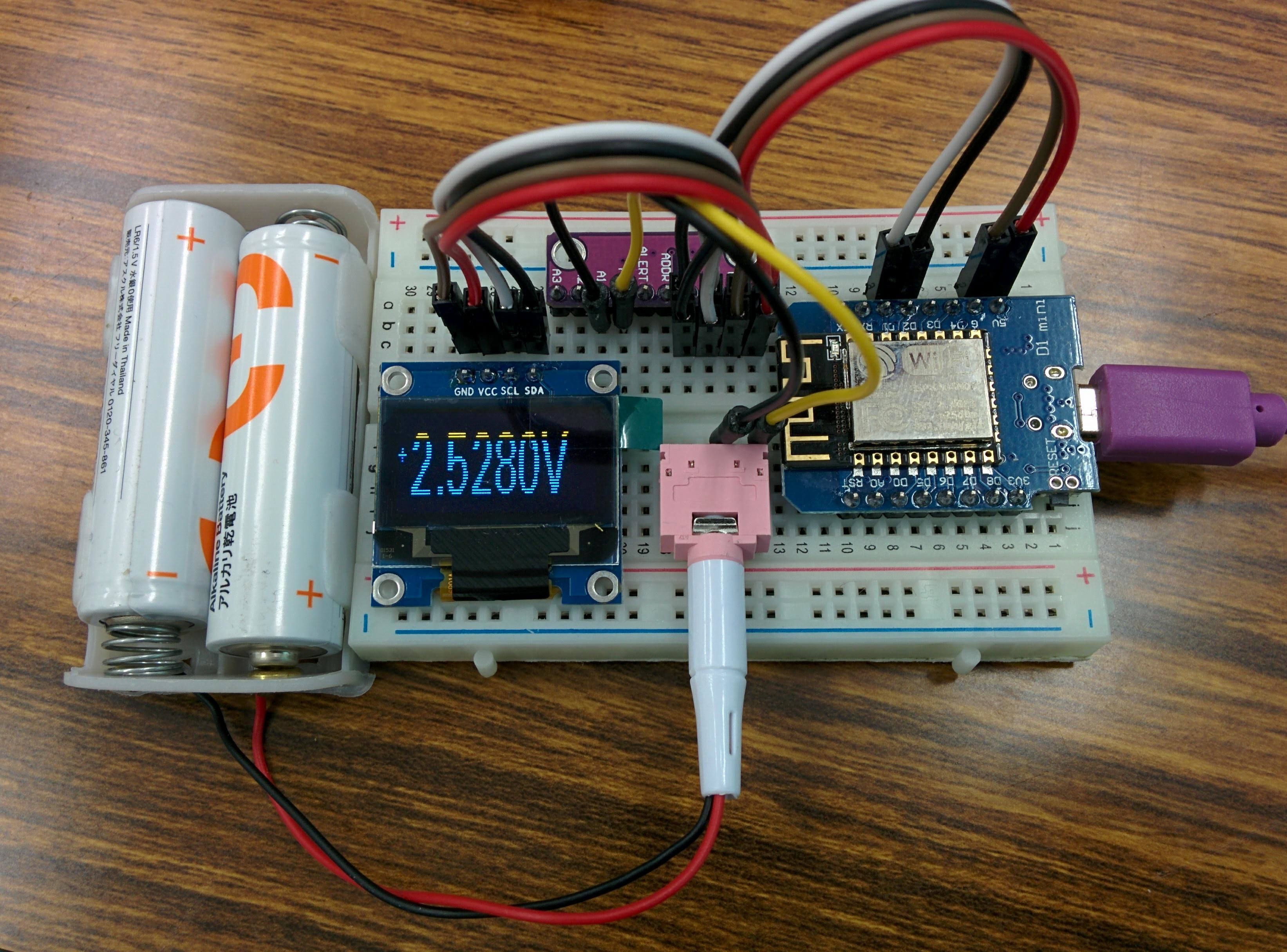
Arduino NANO (7) ADS1115 for A/D できたので、行きよいでOLEDの表示も追加した。
( WeMos (b9) ADS1115 for A/D )とほぼ同じプログラムだが、なぜかうまく表示する、どうして?

表示されるのは2本古い電池の電圧を測る値。
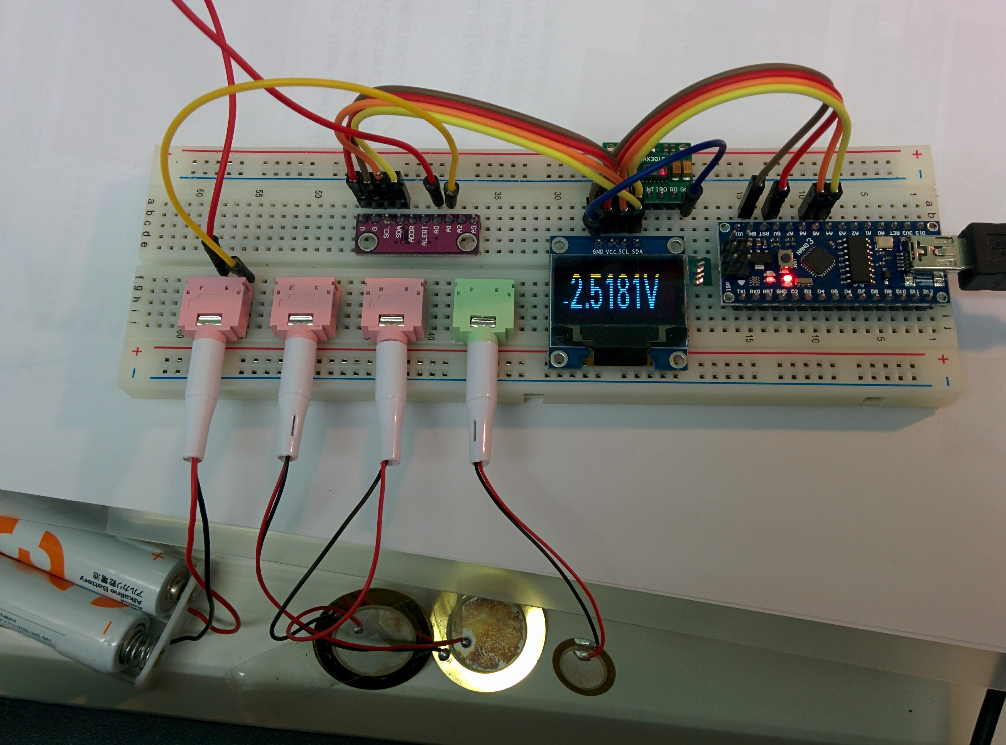
今度ピエゾの電圧も測ってみる。
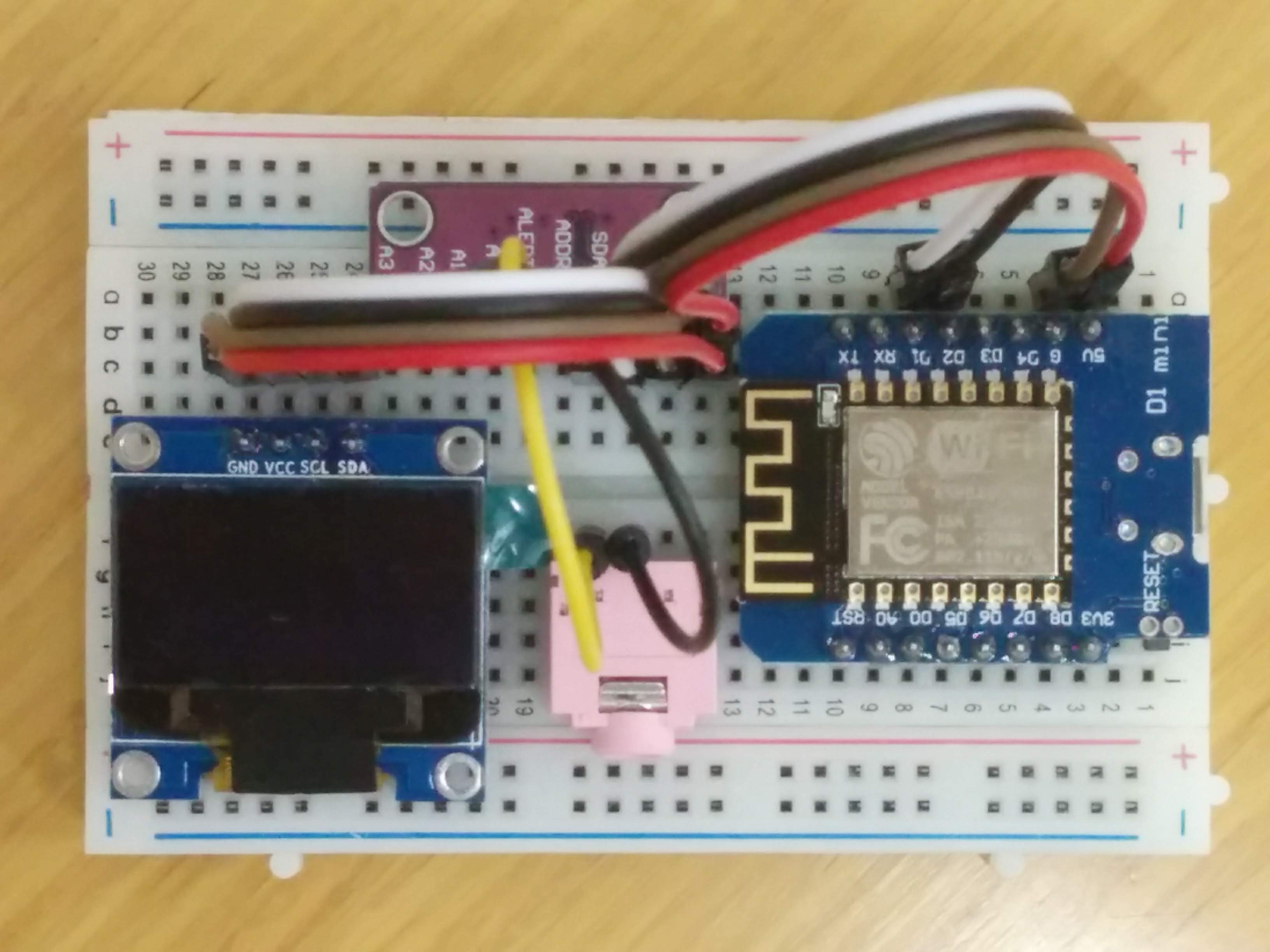
Arduino NANO (8) ADS1115 & OLED
Arduino NANO (7) ADS1115 for A/D できたので、行きよいでOLEDの表示も追加した。
( WeMos (b9) ADS1115 for A/D )とほぼ同じプログラムだが、なぜかうまく表示する、どうして?
表示されるのは2本古い電池の電圧を測る値。
今度ピエゾの電圧も測ってみる。
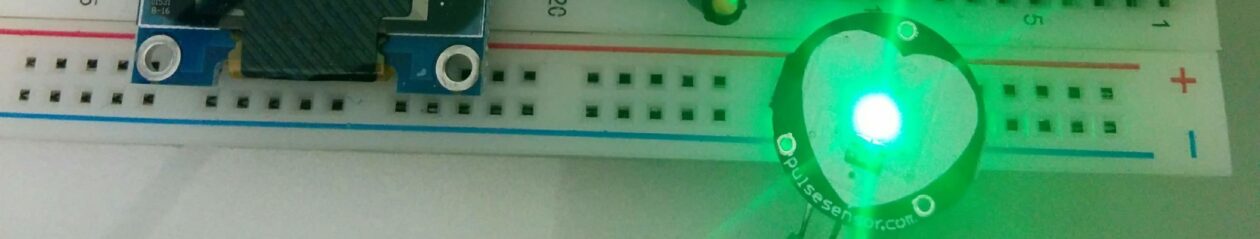
Arduino NANO (6) Heart rate sensor
Arduinoセンサーキットに、Heart rate sensorある。
血中ヘモグロビンの近赤外線吸収の性質を利用して脈拍パルス検出するらしい。
Arduinoとの接続は3線(GND、VCC、アナログ入力)のみ。
「参考1」をみて、まず簡単の試す。ただA0の値を表示。
// Pulse Monitor Test Script
int sensorPin = 0;
void setup() {
   Serial.begin(9600);
}
void loop ()
{
   while(1)
   {
     Serial.print(analogRead(sensorPin));
     Serial.print('\n');
   }
}
指先センサー装着
シリアルプロッターに見える上昇カーブ
安定した状態これはなにもわからない
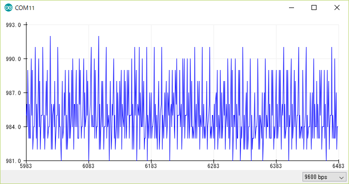
指はセンサーから離れる時の下降カーブ。
「参考1」を参考して、Smoothingしても、同じ判別不能。困った。
#define samp_siz 4
#define rise_threshold 5
// Pulse Monitor Test Script
int sensorPin = 0;
void setup() {
   Serial.begin(9600);
}
void loop ()
{
   float reads[samp_siz], sum;
   long int now, ptr;
   float last, reader, start;
   float first, second, third, before, print_value;
   bool rising;
   int rise_count;
   int n;
   long int last_beat;
   for (int i = 0; i < samp_siz; i++)
     reads[i] = 0;
   sum = 0;
   ptr = 0;
   while(1)
   {
     // calculate an average of the sensor
     // during a 20 ms period (this will eliminate
     // the 50 Hz noise caused by electric light
     n = 0;
     start = millis();
     reader = 0.;
     do
     {
       reader += analogRead (sensorPin);
       n++;
       now = millis();
     }
     while (now < start + 20);
     reader /= n;  // we got an average
     // Add the newest measurement to an array
     // and subtract the oldest measurement from the array
     // to maintain a sum of last measurements
     sum -= reads[ptr];
     sum += reader;
     reads[ptr] = reader;
     last = sum / samp_siz;
     // now last holds the average of the values in the array
     // check for a rising curve (= a heart beat)
     if (last > before)
     {
       rise_count++;
       if (!rising && rise_count > rise_threshold)
       {
         // Ok, we have detected a rising curve, which implies a heartbeat.
         // Record the time since last beat, keep track of the two previous
         // times (first, second, third) to get a weighed average.
         // The rising flag prevents us from detecting the same rise
         // more than once.
         rising = true;
         first = millis() - last_beat;
         last_beat = millis();
         // Calculate the weighed average of heartbeat rate
         // according to the three last beats
         print_value = 60000. / (0.4 * first + 0.3 * second + 0.3 * third);
         Serial.print(print_value);
         Serial.print('\n');
         third = second;
         second = first;
       }
     }
     else
     {
       // Ok, the curve is falling
       rising = false;
       rise_count = 0;
     }
     before = last;
     ptr++;
     ptr %= samp_siz;
   }
}
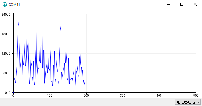
こんな図形になって、周囲の雑音とか酷いかな?
参考:
- https://www.hackster.io/Johan_Ha/from-ky-039-to-heart-rate-0abfca
Arduino NANO (5) MAX30102 Pulse Ox Sensor
試み
MAX30102 というPulse Ox Sensorを利用して、脈拍と酸素濃度を測る試み。
MAX30100の実例が多いが、MAX30102の実例が少ない。
プログラム
「参考1」のSparkFunのライブラリを利用する。そのライブラリはMAX30105(R,G,IR LED)用だが、MAX30102(欠Green LED)でも利用できる。
OLED表示するため、「参考2」の表示部分を合体した。なんとなく、バグがある様な気がする。
// Sample implementation of the MAX30100 PulseOximeter
// Using the following module
// http://www.ebay.com/itm/-/391709438817?ssPageName=STRK:MESE:IT
// can not gaurantee if the app will work with other implementations of the module.

//#include "MAX30100_PulseOximeter.h"
#include <U8g2lib.h>
#include <Wire.h>
#include "MAX30105.h"
#include "heartRate.h"

#define REPORTING_PERIOD_MS     500

 U8G2_SSD1306_128X32_UNIVISION_F_HW_I2C u8g2(U8G2_R0);

// PulseOximeter is the higher level interface to the sensor
// it offers:
//  * beat detection reporting
//  * heart rate calculation
//  * SpO2 (oxidation level) calculation
//PulseOximeter pox;
MAX30105 particleSensor;

const byte RATE_SIZE = 4; //Increase this for more averaging. 4 is good.
byte rates[RATE_SIZE]; //Array of heart rates
byte rateSpot = 0;
long lastBeat = 0; //Time at which the last beat occurred

float beatsPerMinute;
int beatAvg;

//byte pulseLED = 13; //Must be on PWM pin
//byte readLED = 11; //Blinks with each data read
//
bool calculation_complete=false;
bool calculating=false;
bool initialized=false;
byte beat=0;

void show_beat()
{
  u8g2.setFont(u8g2_font_cursor_tf);
  u8g2.setCursor(8,10);
  if (beat==0) {
    u8g2.print("_");
    beat=1;
  }
  else
  {
    u8g2.print("^");
    beat=0;
  }
  u8g2.sendBuffer();
}

void initial_display()
{
  if (not initialized)
  {
    u8g2.clearBuffer();
    show_beat();
    u8g2.setCursor(24,12);
    u8g2.setFont(u8g2_font_profont15_mr);
    u8g2.print("Place finger");
    u8g2.setCursor(0,30);
    u8g2.print("on the sensor");
    u8g2.sendBuffer();
    initialized=true;
  }
}

void display_calculating(int j)
{
  if (not calculating) {
    u8g2.clearBuffer();
    calculating=true;
    initialized=false;
  }
  show_beat();
  u8g2.setCursor(24,12);
  u8g2.setFont(u8g2_font_profont15_mr);
  u8g2.print("Measuring...");
  u8g2.setCursor(0,30);
  u8g2.print(beatsPerMinute);
  u8g2.print(" Bpm");
  u8g2.sendBuffer();
}

void display_values()
{
  u8g2.clearBuffer();
  u8g2.setFont(u8g2_font_profont15_mr);

  u8g2.setCursor(0,30);
  u8g2.print(beatsPerMinute);
  u8g2.print(" Bpm _ ");
  u8g2.setCursor(65,30);
  u8g2.print(beatAvg);
  u8g2.sendBuffer();
}

void setup()
{
    Serial.begin(115200);

//    pinMode(pulseLED, OUTPUT);
//    pinMode(readLED, OUTPUT);

    u8g2.begin();

    // Initialize sensor
    if (!particleSensor.begin(Wire, I2C_SPEED_FAST)) //Use default I2C port, 400kHz speed
    {
      Serial.println(F("MAX30105 was not found. Please check wiring/power."));
      while (1);
    }

    particleSensor.setup(); //Configure sensor with default settings
    particleSensor.setPulseAmplitudeRed(0x0A); //Turn Red LED to low to indicate sensor is running
    particleSensor.setPulseAmplitudeGreen(0); //Turn off Green LED

    initial_display();
}


void loop()
{

  long irValue = particleSensor.getIR();
  float temperature = particleSensor.readTemperature();
//  digitalWrite(readLED, !digitalRead(readLED)); //Blink onboard LED with every data read

  if (checkForBeat(irValue) == true)
  {
    calculation_complete=true;
    calculating=false;
    initialized=false;

//    digitalWrite(pulseLED, !digitalRead(pulseLED)); //Blink onboard LED with every Beat
    //We sensed a beat!
    long delta = millis() - lastBeat;
    lastBeat = millis();

    if (delta < 10000) {
      beatsPerMinute = 60 / (delta / 1000.0);
    } else {
      calculation_complete=false;
      beatsPerMinute=0;
      initial_display();
    }

    if (beatsPerMinute < 255 && beatsPerMinute > 20)
    {
      rates[rateSpot++] = (byte)beatsPerMinute; //Store this reading in the array
      rateSpot %= RATE_SIZE; //Wrap variable

      //Take average of readings
      beatAvg = 0;
      for (byte x = 0 ; x < RATE_SIZE ; x++)
        beatAvg += rates[x];
      beatAvg /= RATE_SIZE;
      display_values();
    }
  } else {
    if (irValue < 50000) {
      calculating=false;
      initial_display();
    } else {
      display_calculating(5);
    }
  }

  Serial.print("IR=");
  Serial.print(irValue);
  Serial.print(", BPM=");
  Serial.print(beatsPerMinute);
  Serial.print(", Avg BPM=");
  Serial.print(beatAvg);
  Serial.print(", initialized=");
  Serial.print(initialized);
  Serial.print(", calculating=");
  Serial.print(calculating);
  Serial.print(", calculation_complete=");
  Serial.print(calculation_complete);
  Serial.println();


}
実験
かなり不安定の感じがする。
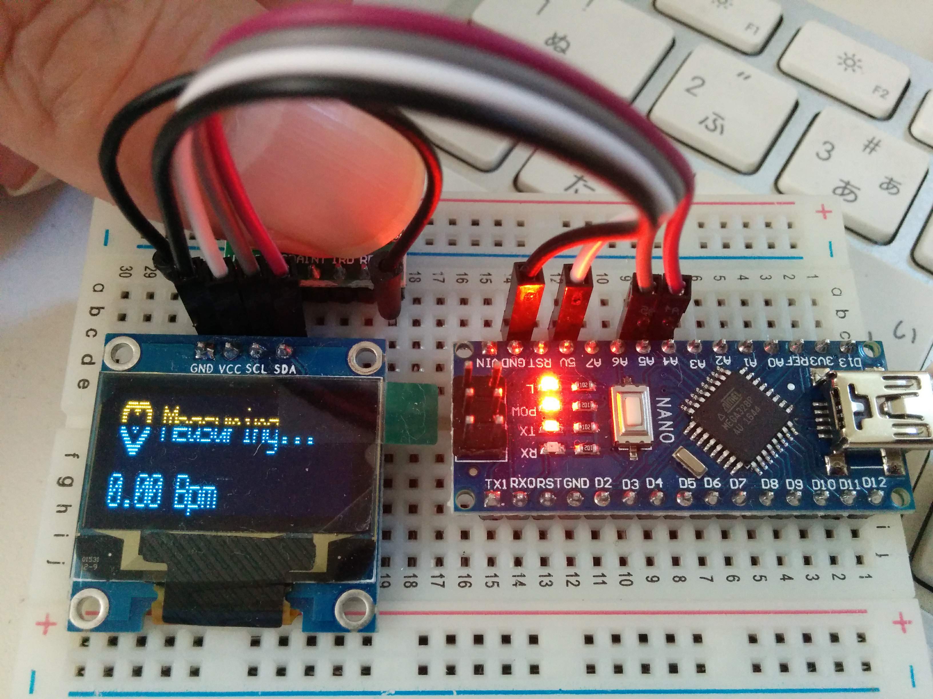
一応、形はできたが、
しかし、脈拍捉えるのは稀て、今回も失敗して。。。
参考
- https://learn.sparkfun.com/tutorials/max30105-particle-and-pulse-ox-sensor-hookup-guide
- https://www.hackster.io/umar-sear/arduino-heart-rate-monitor-a8e9e1
- https://www.hackster.io/AAKS/max30100-and-blynk-0f58f4
Arduino NANO (4) Piezoelectric sensor
なぜ
Piezoelectric sensorを利用して、住宅内の音声、振動から年配者の介護の補助を考えている。
Piezoelectric sensorが取った情報をAD変換して、簡単にWemosで処理すると思ったが、いろいろ意外なところで躓いた。
何か類似する、簡単に検証できる例がないか探した。
取り込み
「参考1」から、普通のPiezoelectric sensorで、簡単に脈拍を取れると、魅力と思った。
必要な部品が揃うまで時間がかかったが、一応出来た。
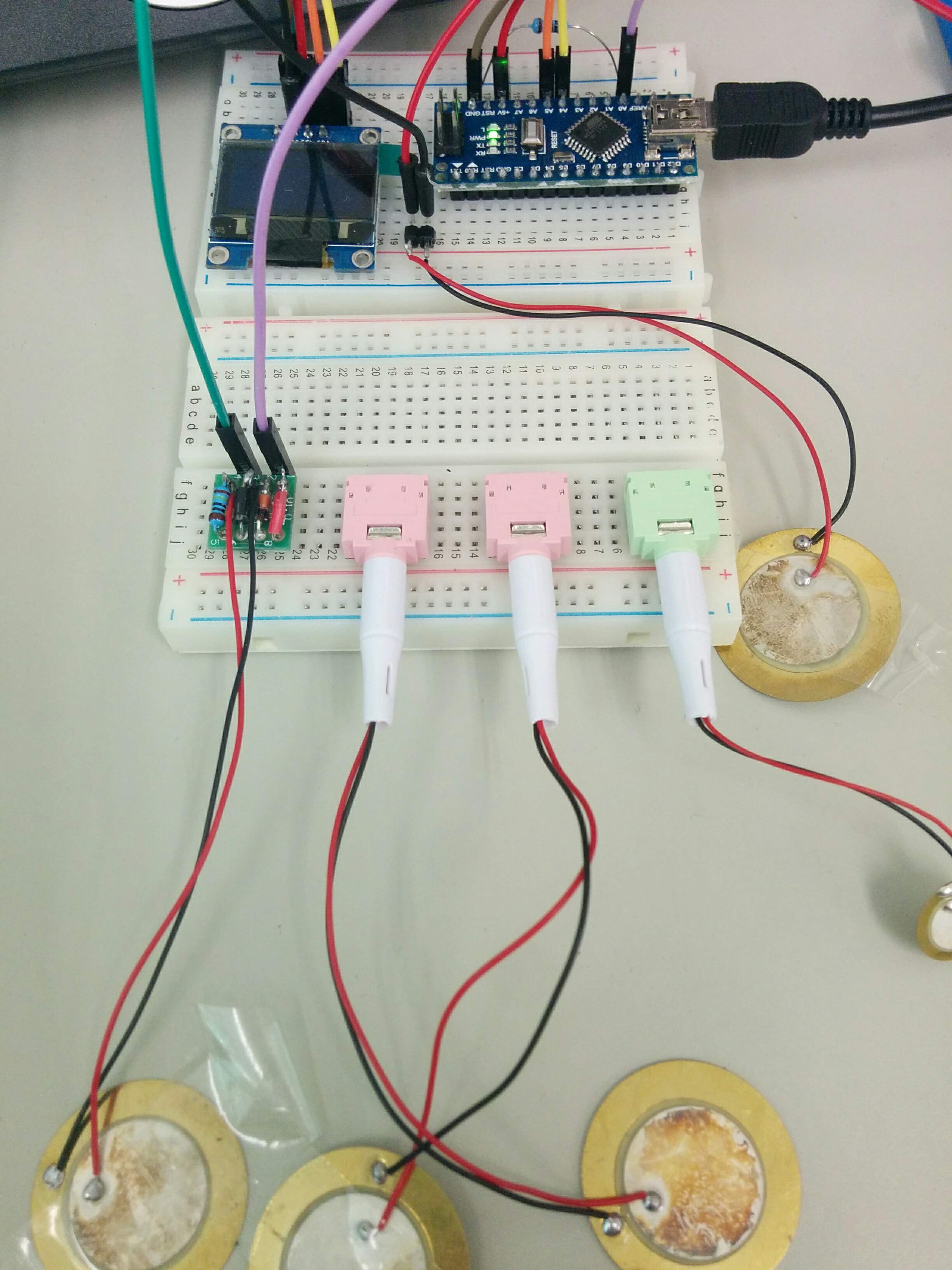
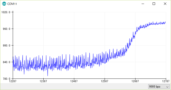
いろいろと試したところ
拡大写真
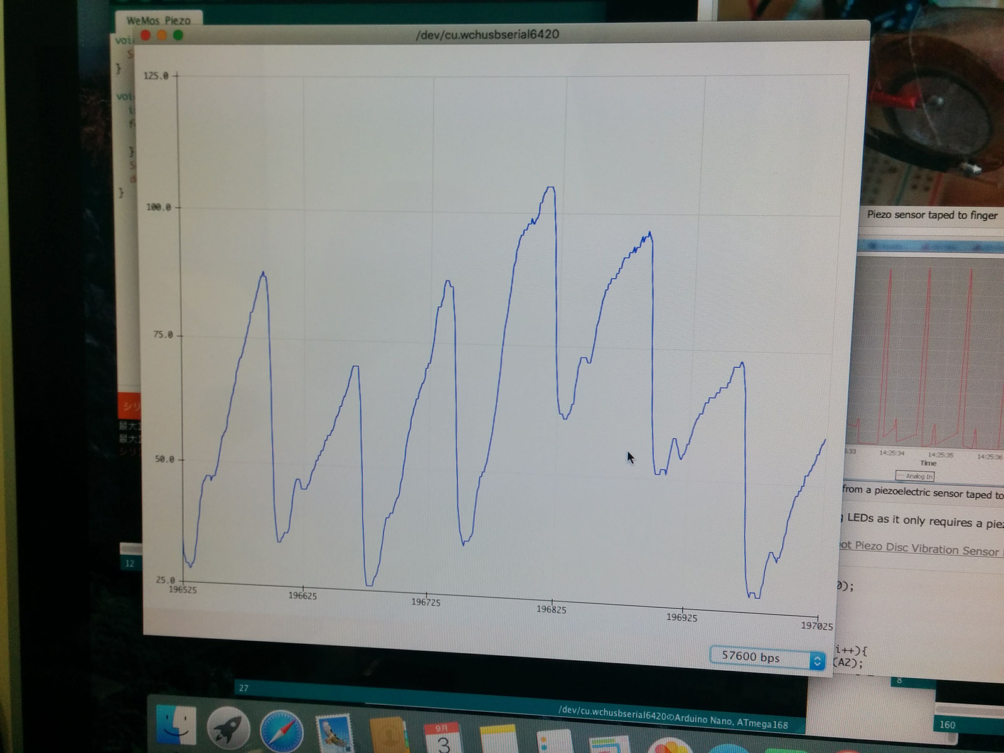
取れた波形。「参考1」の波形には似ているは、DC成分あるから、取り除くが課題。
参考
- http://www.ohnitsch.net/2015/03/18/measuring-heart-rate-with-a-piezoelectric-vibration-sensor/
WeMos (b10) ADS1115 Oscilloscope
前回WeMos (b9) ADS1115 for A/Dで数値の表示ができたが、Oscilloscopeのような表示すべく、改造を試み。
しかし、2月から、WeMos miniの開発中も頻繁にリブートしています。デバイストライバのバージョンを変えたり、OSを変えたりしても改善しない。
そのため、このプログラムは未完成のまま放置。
/*
This is set up to use a 128x64 I2C screen, as available
here: http://www.banggood.com/buy/0-96-oled.html
For wiring details see http://youtu.be/XHDNXXhg3Hg
*/
#include <SPI.h>
#include <Wire.h>
#include <limits.h>
#include <Adafruit_GFX.h>
#include <Adafruit_SSD1306.h>
#include <Adafruit_ADS1015.h>
#include <math.h>
#define WINDOW_SIZE 128
Adafruit_ADS1115 ads;  /* Use this for the 16-bit version */
//Adafruit_ADS1015 ads;     /* Use thi for the 12-bit version */
#define OLED_RESET 0    // 4
Adafruit_SSD1306 display(OLED_RESET);
#if (SSD1306_LCDHEIGHT != 64)
//  error("Height incorrect, please fix Adafruit_SSD1306.h!");
#endif
/********************************************/
#define CHARWIDTH           5
#define CHARHEIGHT          8
#define AXISWIDTH           (2 + 1)                   // axis will show two-pixel wide graph ticks, then an empty column
#define VISIBLEVALUEPIXELS  (128 - AXISWIDTH)         // the number of samples visible on screen
#define NUMVALUES           (2 * VISIBLEVALUEPIXELS)  // the total number of samples (take twice as many as visible, to help find trigger point
#define TRIGGER_ENABLE_PIN       D6  // 2 set this pin high to enable trigger
#define SCREEN_UPDATE_ENABLE_PIN D8  // 3 set this pin high to freeze screen
byte values[NUMVALUES];           // stores read analog values mapped to 0-63
int pos = 0;                      // the next position in the value array to read
int count = 0;                    // the total number of times through the loop
unsigned long readStartTime = 0;  // time when the current sampling started
int sampleRate = 1;              // A value of 1 will sample every time through the loop, 5 will sample every fifth time etc.
// Draws the graph ticks for the vertical axis
void drawAxis()
{
  // graph ticks
  for (int x = 0; x < 2; x++) {
    display.drawPixel(x,  0, WHITE);
    display.drawPixel(x, 13, WHITE);
    display.drawPixel(x, 26, WHITE);
    display.drawPixel(x, 38, WHITE);
    display.drawPixel(x, 50, WHITE);
    display.drawPixel(x, 63, WHITE);
  }
}
// Draws the sampled values
void drawValues()
{
  int start = 0;
  if ( digitalRead(TRIGGER_ENABLE_PIN) ) {
    // Find the first occurence of zero
    for (int i = 0; i < NUMVALUES; i++) {
      if ( values[i] == 0 ) {
        // Now find the next value that is not zero
        for (; i < NUMVALUES; i++) {
          if ( values[i] != 0 ) {
            start = i;
            break;
          }
        }
        break;
      }
    }
    // If the trigger point is not within half of our values, we will
    // not have enough sample points to show the wave correctly
    if ( start >= VISIBLEVALUEPIXELS )
      return;
  }
  for (int i = 0; i < VISIBLEVALUEPIXELS; i++) {
    display.drawPixel(i + AXISWIDTH, 63 - (values[i + start]), WHITE);
  }
}
// Shows the time taken to sample the values shown on screen
void drawFrameTime(unsigned long us)
{
  display.setCursor(9 * CHARWIDTH, 7 * CHARHEIGHT - 2); // almost at bottom, approximately centered
  display.print(us);
  display.println(" us");
}
/********************************************/
void setup() {
  // The ADC input range (or gain) can be changed via the following
  // functions, but be careful never to exceed VDD +0.3V max, or to
  // exceed the upper and lower limits if you adjust the input range!
  // Setting these values incorrectly may destroy your ADC!
  //                                                                ADS1015  ADS1115
  //                                                                -------  -------
     ads.setGain(GAIN_TWOTHIRDS);  // 2/3x gain +/- 6.144V  1 bit = 3mV      0.1875mV (default)
  // ads.setGain(GAIN_ONE);        // 1x gain   +/- 4.096V  1 bit = 2mV      0.125mV
  // ads.setGain(GAIN_TWO);        // 2x gain   +/- 2.048V  1 bit = 1mV      0.0625mV
  // ads.setGain(GAIN_FOUR);       // 4x gain   +/- 1.024V  1 bit = 0.5mV    0.03125mV
  // ads.setGain(GAIN_EIGHT);      // 8x gain   +/- 0.512V  1 bit = 0.25mV   0.015625mV
  // ads.setGain(GAIN_SIXTEEN);    // 16x gain  +/- 0.256V  1 bit = 0.125mV  0.0078125mV
  ads.begin();
  // Set up the display
  display.begin(SSD1306_SWITCHCAPVCC, 0x3C); // Initialize with the I2C addr 0x3D (for the 128x64)
  display.setTextColor(WHITE);
  pinMode(TRIGGER_ENABLE_PIN, INPUT);
  pinMode(SCREEN_UPDATE_ENABLE_PIN, INPUT);
}
/********************************************/
void loop() {
  // If a sampling run is about to start, record the start time
  if ( pos == 0 )
    readStartTime = micros();
  // If this iteration is one we want a sample for, take the sample
  if ( (++count) % sampleRate == 0 )
    values[pos++] = (ads.readADC_SingleEnded(0)>> 7) / 3; // shifting right by 4 efficiently maps 0-1023 range to 0-63
//    values[pos++] = analogRead(0) >> 4; // shifting right by 4 efficiently maps 0-1023 range to 0-63
  // If we have filled the sample buffer, display the results on screen
  if ( pos >= NUMVALUES ) {
    // Measure how long the run took
    unsigned long totalSampleTime = (micros() - readStartTime) / 2;     // Divide by 2 because we are taking twice as many samples as are shown on the screen
    if ( !digitalRead(SCREEN_UPDATE_ENABLE_PIN) ) {
      // Display the data on screen
      display.clearDisplay();
      drawAxis();
      drawValues();
      drawFrameTime(totalSampleTime);
      display.display();
    }
    // Reset values for the next sampling run
    pos = 0;
    count = 0;
  }
}
Arduino NANO (3) SSH1106 & Walking bitmap
経緯
ちょっと大き目のOLEDが欲しくて、1.3 InchのOLEDを注文した。
ただもの挿し替えて使えると思って、届いてわかったが、コントローラーは別物。SH1106というものを使われ、U8g2libライブラリをインストールして利用する。
Display OLED via I2C (SH1106)
実際参考サイトを見ながら、試してみる。

うまく表示できた。
しかしコントローラーが特殊のため、使用例がほとんど無いので、用途が限定。
Script – Walking bitmap
#include <Arduino.h>
#include <U8g2lib.h>

#ifdef U8X8_HAVE_HW_SPI
#include <SPI.h>
#endif
#ifdef U8X8_HAVE_HW_I2C
#include <Wire.h>
#endif

U8G2_SH1106_128X64_NONAME_F_HW_I2C u8g(U8G2_R0, /* reset=*/ U8X8_PIN_NONE);
// U8GLIB_SH1106_128X64 u8g(U8G_I2C_OPT_NONE); // I2C / TWI

const uint8_t bm[] PROGMEM = {
  0b00011000,
  0b00111100,
  0b01111110,
  0b11111111,
  0b11111111,
  0b01111110,
  0b00111100,
  0b00011000
};

static int WIDTH=128;
static int HEIGHT=64;

int x, y;

void setup(void) {
  u8g.begin();
  x = 0;
  y = 0;
}

void loop(void) {

  u8g.firstPage();
  do {
    u8g.drawBitmap( x, y, 1, 8, bm);
  } while( u8g.nextPage() );

  delay(100);

  x += 8;
  if( x >= WIDTH){
    x = 0;
    y += 8;
    if( y >= HEIGHT){
      y = 0;
    }
  }
}
参考
WeMos (b9) ADS1115 for A/D
ADS1115とは
ADS1115 とは4チャンネル16bit A/D 。I2C接続なので、OLEDと共に、WeMos に接続して利用してみる。


結線
SCL, SDA自由に変更可能。U8g2初期化コマンドでSetupする。
code
#include <Wire.h>
#include <Adafruit_ADS1015.h>
#include <U8g2lib.h>
#include <math.h>
#define WINDOW_SIZE 128
Adafruit_ADS1115 ads;  /* Use this for the 16-bit version */
//Adafruit_ADS1015 ads;     /* Use thi for the 12-bit version */
// Sets up the display to be the 128px x 32px display
U8G2_SSD1306_128X32_UNIVISION_F_HW_I2C u8g2(U8G2_R0, /* reset=*/ U8X8_PIN_NONE, /* clock=*/ SCL, /* data=*/ SDA);
void setup(void)
{
  Serial.begin(9600);
  Serial.println("Hello!");
  Serial.println("Getting differential reading from AIN0 (P) and AIN1 (N)");
  Serial.println("ADC Range: +/- 6.144V (1 bit = 3mV/ADS1015, 0.1875mV/ADS1115)");
  // The ADC input range (or gain) can be changed via the following
  // functions, but be careful never to exceed VDD +0.3V max, or to
  // exceed the upper and lower limits if you adjust the input range!
  // Setting these values incorrectly may destroy your ADC!
  //                                                                ADS1015  ADS1115
  //                                                                -------  -------
  ads.setGain(GAIN_TWOTHIRDS);  // 2/3x gain +/- 6.144V  1 bit = 3mV      0.1875mV (default)
  // ads.setGain(GAIN_ONE);        // 1x gain   +/- 4.096V  1 bit = 2mV      0.125mV
  // ads.setGain(GAIN_TWO);        // 2x gain   +/- 2.048V  1 bit = 1mV      0.0625mV
  // ads.setGain(GAIN_FOUR);       // 4x gain   +/- 1.024V  1 bit = 0.5mV    0.03125mV
  // ads.setGain(GAIN_EIGHT);      // 8x gain   +/- 0.512V  1 bit = 0.25mV   0.015625mV
  // ads.setGain(GAIN_SIXTEEN);    // 16x gain  +/- 0.256V  1 bit = 0.125mV  0.0078125mV
  // Initialize the display
  u8g2.begin();
  ads.begin();
}
// Function to print ${value} with a specific number of ${digits}
void print_digits(double value, short unsigned digits){
  double av = abs(value);
  value = av;
  while(av > 10){
    digits--;
    av/=10;
  }
  u8g2.print(value, digits - 1);
}
int16_t results[WINDOW_SIZE] = {0};
int current_result = 0;
void loop(void)
{
 int time = millis();
  /* Be sure to update this value based on the IC and the gain settings! */
  //float   multiplier = 3.0F;    /* ADS1015 @ +/- 6.144V gain (12-bit results) */
  float multiplier = 0.1875F; /* ADS1115  @ +/- 6.144V gain (16-bit results) */
  double voltage_multiplier = 5333;
  for (int i = 0; i < 16; i++){
    results[current_result] = ads.readADC_Differential_0_1();
    current_result++;
    current_result = current_result % WINDOW_SIZE;
  }
  double result = 0;
  int i;
  for (i = 0; i < WINDOW_SIZE; i++){
    result = result + results[i];
  }
  result = result / (double) WINDOW_SIZE;
  /*Serial.print("Differential: "); Serial.print(results); */
   //Serial.print("(");
   Serial.println(result * multiplier, 5);
   //Serial.println("mV)");
  u8g2.firstPage();
  do {
    // this is where the values get printed to the display
    //u8g2.setFont(u8g2_font_logisoso32_tr); // large 32px tall font
    // other font options can be found at https://github.com/olikraus/u8g2/wiki/fntlistall
    u8g2.setFont(u8g2_font_6x12_tn);
    if (result > 0){
      u8g2.setCursor(0,16);
      u8g2.print("+");
    } else {
      u8g2.setCursor(0,26);
      u8g2.print("-");
    }
    u8g2.setFont(u8g2_font_fur20_tr); // large 20px tall font
    u8g2.setCursor(7,26 );
    double volts = result / voltage_multiplier;
    print_digits(volts, 5);
    u8g2.print("V");
  } while ( u8g2.nextPage() );
  int d = (1000 / 16) - (millis() - time);
  if (d > 0){
    delay(d);
  }
}
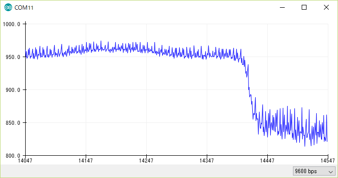
動作確認
しかし、テスト結果は、思う通りにならない。
表示は0.0000V、1.0000V、ー1.0000V、の感じで、小数点以下は0000となっている。どうして?
大変の曲がり道して、わかったのは、OLEDの定義が間違え、「U8G2_SH1106_128X64_NONAME_F_HW_I2C」になって、その影響で、読み取り数字が変に。
「U8G2_SSD1306_128X32_UNIVISION_F_HW_I2C」で定義を直したら、普通にA/D変換の結果が表示が出来た。
参考
IoT 見守りデバイスの開発
見守りIoTデバイスは、ウェアフリー生体センサ・シート型圧電センサと開発ボード、電源で構成された。
シート型圧電センサ
本研究では体動がなく静かな状態で得られた生体信号を分析対象とする。センサは敏感すぎて 体動があると、振幅が大大き過ぎになり、それらが検出できなくなる。
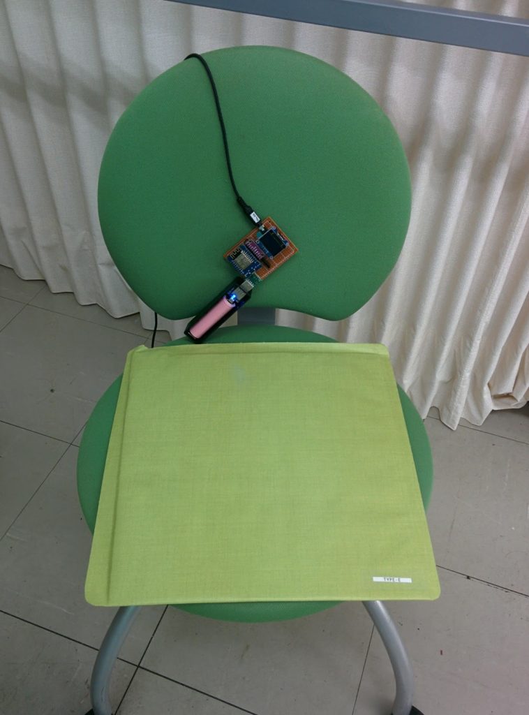
図 4.2 センサシートと開発ボード
今回使用したシート型圧電センサの外形寸法(31cm×34cm)により、椅子の座面に敷いた 状態で測定することにした(図 3.2 右側)。座り状態で安定しやすくなり、血圧や脈拍も測 定しやすくなる。本センサでは 得られた信号は呼吸成分や心拍成分でできている。
見守り開発ボード
見守り開発ボードにはA/D変換モジュールADS1115、ESP8266マイクロコントローラ内蔵の開発ボードWeMos D1 Miniと、OLED表示モジュール SSD1306が含まれる。

WeMos D1 MiniとはESP8266をメインチップとして、CH340のUSBシリアル変換チップを組み合わせた開発ボードだ。ESP8266マイクロコントローラはWi-Fiネットワークに接続し、簡単なTCP/IP接続を行うことができる。
ADS1115は可変ゲインアンプ付き、4チャンネル内蔵の16bit A/D コンバータ。I2Cというシリアル通信方法で開発ボードに接続する。
SSD1306は小型 解像度128×64 OLED ディスプレイである。こちらもI2Cというシリアル通信方法で開発ボードに接続する。
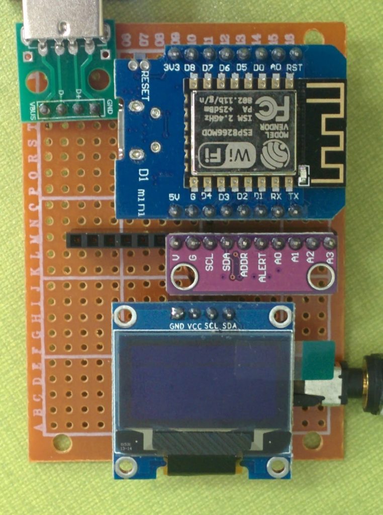
図 4.3 見守りIoTボード
UPDとの通信はUPD APIを利用する。データをUPDへ送信と、UPDから見守り開発ボードへの管理コマンド受信に利用されている。送受信データのTAGは、複数の個体を区別するため、マイクロコントローラのMACアドレスの一部を利用する。例えば見守りIoTボードのMACアドレス下6桁は37cb33のマイクロコントローラに対して、ゲインを4に設定する場合は、TAGは gain-37cb33 である。
ウェアフリー生体センサからのデータをサンプリング周波 数 100Hz でデータを取得し、A/D変換して保存する。一定期間のデータを収集したら、まとめてUPDへ送信する。データサンプルは付録1を参照。一度にデータの収集できる期間は、見守りデバイスマイクロコントローラの内蔵メモリの容量による。
ESP8266マイクロコントローラの場合、メモリのリミットにより、6 秒間のデータの蓄積、送信できた。プログラムの最適化により、より長い期間のデータの蓄積、送信も可能である。
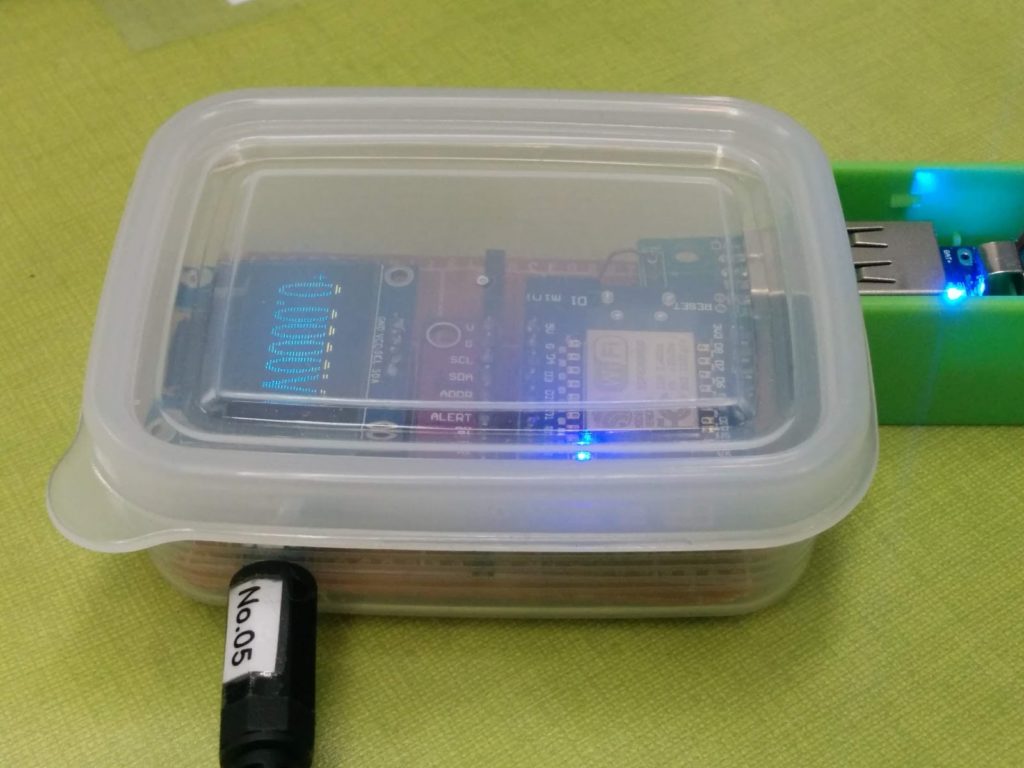
図 4.4 ケースにいれた見守りIoTボード
見守りIoTボードUPDから見守りデバイスへの管理コマンドの受信も可能である。
ADS1115は可変ゲインアンプであり、現在実装したコマンドはそのゲインの設定である。次はADS1115のゲインを指示するコマンドのサンプルである。
“VALUE” “gain-37cb33” “4”
われわれ開発した見守りIoTデバイスのプログラムはGitHubのリポジトリを参照する。
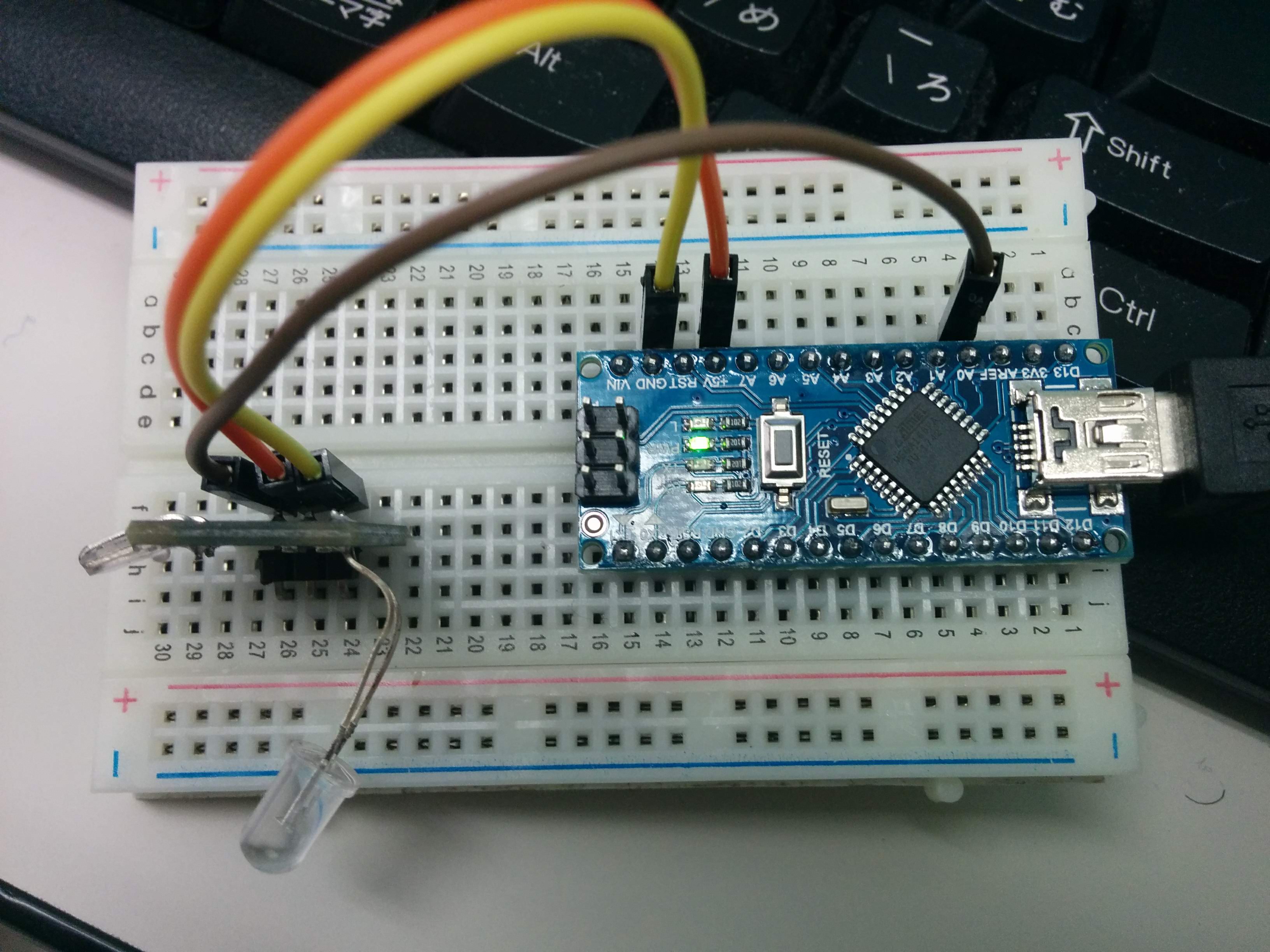
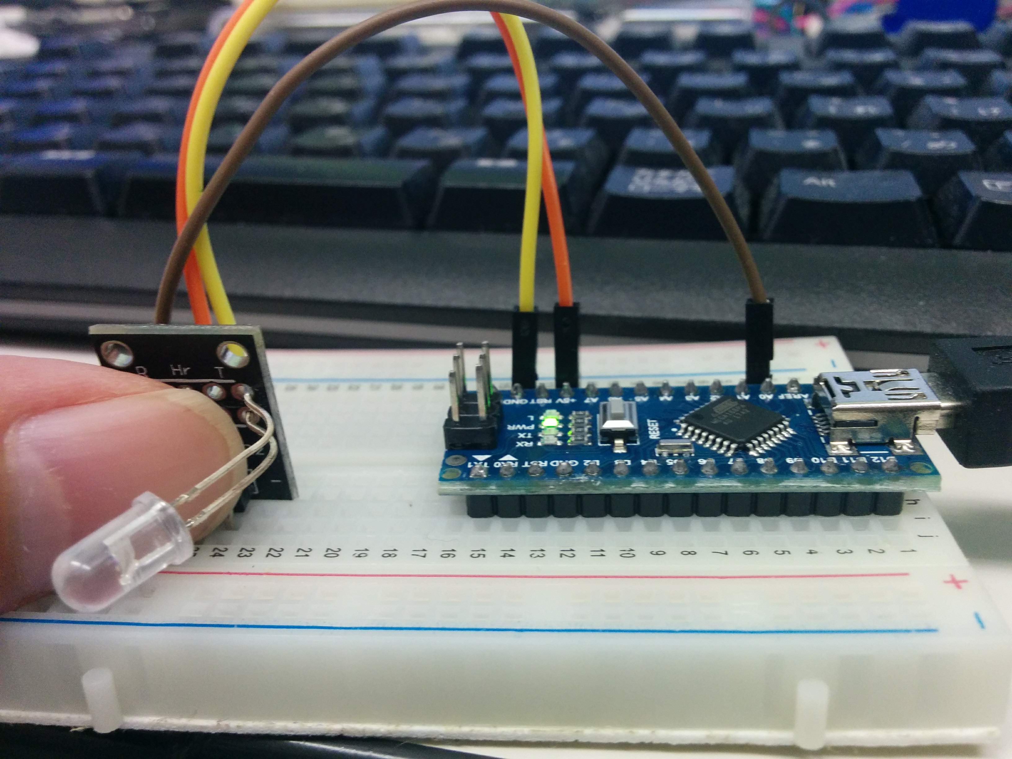
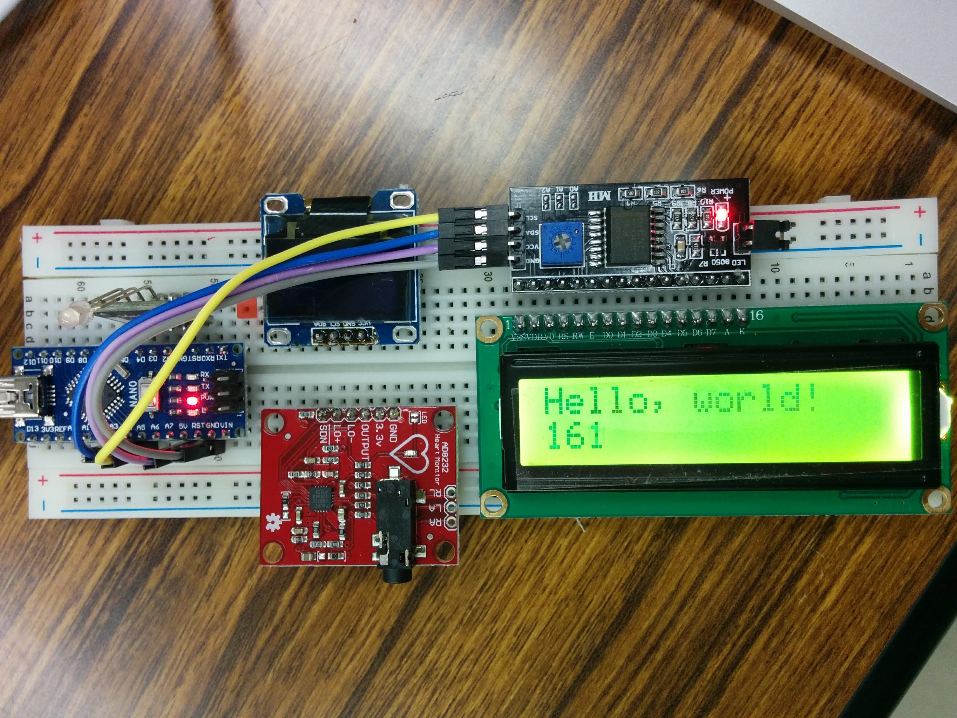
Arduino NANO (1) AD8232 Heart Rate Monitor
経緯
IoT材料を探しに、AD8232 Heart Rate Monitor パーツを購入しました。
添付資料は何もないので、ネットで検索したら、結構出ました。
目の動きも検出できる、いろいろできそう。
回路
参考資料は、Arduino NANOを利用するので、そのままの回路を組み立てる予定。成功したら、ESP8266,ESP32に移植するつもり。
The detailed specification of the Arduino Nano board is as follows:
-
- Microcontroller ATmega328
- Operating Voltage (logic level): 5 V
- Input Voltage (Recommended): 7-12 V
- Input Voltage (limits): 6-20 V
- Digital I/O Pins : 14 (of which 6 provide PWM Output)
- Analog Input Pins: 8
- DC Current per I/O Pin: 40 mA
- Flash Memory 32 KB (ATmega328) of which 2 KB used by bootloader
- SRAM: 2 KB (ATmega328)
- EEPROM: 1 KB (ATmega328)
- Clock Speed: 16 MHz
- Measurements: 0.73″ x 1.70″
Arduino NANOとAD8232をつないて、LCDまたはOLEDで表示するつもりだが、安定した結果は出ないので、部品の問題か、ソフトウェアの問題か、解決に難航。
部品を買い増すして、検証する予定。
スケッチ
参考資料
- https://learn.sparkfun.com/tutorials/ad8232-heart-rate-monitor-hookup-guide